Atmega Based Thermostat Part 2
In my previous blog post, I discussed the hardware selection for building my own thermostat. In this post, I am covering the software side of things. Since then I've revised the hardware a small amount. I moved to relays that can run from 5 volts DC and are physically smaller. The layout has been redone. I made sure to have the USB connector of the microcontroller point off the edge of the board so it would be accessible without removing the micrcocontroller from its socket.
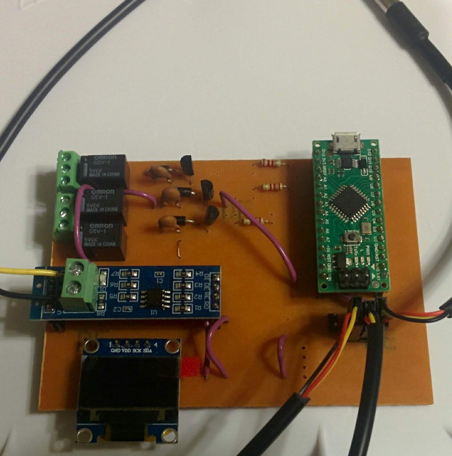
This is my revised board design, which is hopefully easier to use
Compiler & toolchain
The first thing that is critical is picking a compiler and the associated toolchain. Most 8-Bit microprocessorss do not feature self-hosting toolchains, so you need to be able to run the compiler on a personal computer. The most popular choice for this is the Arduino platform. But the Arduino platform doesn't officially support my chosen microcontroller, the Atmega328PB. So I opted to use the AVR GCC port. This is a port of GCC that can produce a complete image that runs on an Atmega chip. I'm comfortable programming in C and I have been for some time. I appreciate the simple design of the language and the amount of freedom it gives you over the implementation. The avr-gcc compiler runs on most desktop platforms including Linux & Windows. If you use Ubuntu, you can find it in the package repositories. I actually did quite a bit of development for this project on a Raspbery Pi 3 that was sitting on my workbench at the time. It had enough computing power available that I could compile the entire project in about 20 seconds.
The Atmega328PB is an official, supported part but is not in the latest release of avr-gcc. Instead, you need to go download a device pack that contains all the necessary header files to support the latest devices from Atmega.
One other important change I made was updating to the latest version of Optiboot. Optiboot is a bootloader for Atmega chips like the one I am using. You don't actually need to program the microcontroller with a bootloader at all, you can just program it via ICSP. But I find it more convenient to use the USB port that is available. For this you'll need to use a bootloader. I updated to the latest version of Optiboot since I had literally no idea what was on the microcontroller when it was shipped to me.
To actually write the software image to the chip I used avrdude which is also from the Ubuntu repositories. Just like avr-gcc it is capable of writing to the Atmega328PB but doesn't know about the chip yet. I edited the file /etc/avrdudue.conf and then added this to the end
part parent "m328"
    id                  = "m328pb";
    desc                = "ATmega328PB";
    signature           = 0x1e 0x95 0x16;

    ocdrev              = 1;

    memory "efuse"
                size = 1;
                min_write_delay = 4500;
                max_write_delay = 4500;
                read = "0 1 0 1 0 0 0 0 0 0 0 0 1 0 0 0",
                           "x x x x x x x x o o o o o o o o";

                write = "1 0 1 0 1 1 0 0 1 0 1 0 0 1 0 0",
                                "x x x x x x x x x x x x i i i i";
    ;

;
Afterwards avrdude was able to program the Atmega328PB.
Reading the DS18B20 sensors
In order to read the digital temperature sensors I chose, you need to be able to communicate over a 1-wire bus. The protocol is simple enough, but I had no interest in implementing it myself. I eventually found this library by Jacajack called avr-ds18b20. The library is simple and to the point. It uses a technique known as bit banging. This means it can communicate over any digital IO pin on the chip, which is basically all of them. All the timing of communication is managed in software.
Each temperature sensor has its own globally unique ID assigned to it that is 8 bytes long. The library includes a function named ds18b20search that can be used to discover the 8 byte string of currently attached temperature sensors. I chose to store the sensor IDs in the EEPROM of the microcontroller. I added a check during startup to see if the stored values are just 0xFF repeating. If it is, the ds18b20search function is invoked. If 3 sensors are found those values are written into the EEPROM and then the microcontroller is reset.
The eight bytes consumed by the sensor ID doesn't seem like much, but this value must be used each time the sensor is communicated with. Since reading the EEPROM is slow, I allocated some byte arrays to store the actual values at runtime. Since I am using 3 sensors, this means that it actually consumes 24 bytes of available memory. This is mostly an implementation decision on my part, but 24 bytes of memory consumption is quite significant in an embedded application. I could instead store the sensor ID in program space, but this means the image programmed to the microcontroller would have to be customzied to each set of sensors.
Making sense of the temperature values
Since these temperature sensors are digital, they return a reading that is just a 16-bit number. The sensor has an actual limitation of 12-bit of resolution so 4 of them are meaningless. The remaining bits are an approximation of the actual temperature at the sensor. It's possible to work with this 12-bit number directly, but is not intuitive. So I wanted to convert it to a floating point number. This chart shows the relationship between the bits and the values each one represents.
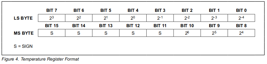
This table is taken directly from the Maxim datasheet for the part. Copyright Maxim Integrated
The above table indicates that the top 4 bits are the sign bit. Bits 4-10 are really no different than any normal integer value, where each bit represents a power of 2. Bits 0-3 represent fractional powers of 2, since the temperature sensor has a resolution that is greater than 1 degree celsius. If this idea isn't familiar to you, further explanation is available here.
So I needed to come up with an easy to understand algorithm that converts this. This is my actual implementation
float ds18b20_temp_to_float(uint16_t input){
  uint8_t i;
  uint16_t b;
  uint16_t v;
  float result = 0.0;

  // Convert the integer part
  v = 1<<6;
  b = 1<<10;
  i = 10;
  for(;i != 3;i--, v >>=1, b>>=1){
    if(0 != (input & b)){
      result += v;
    }
  }

  // Convert the fractional part
  v = 1<<1;
  b = 1<<3;
  i = 3;
  for(; i != UINT8_MAX; i--, v<<=1 , b>>=1){
    if(0 != (input & b)){
      result += 1.0/((float)v);
    }
  }

  // Check if negative
  if (0 != (input & (1<<11))){
    result *= -1.0;
  }

  return result;
}
The above code does the following:
- Initializes the
resultto zero. - Steps across the bits for the positive integer values, adding the associated value if the bit is set
- Steps across the bits for the fractional integer values, adding the associated value if the bit is set
- Multiplies by negative one if the sign bit is set
Since the result is a floating point number, there is no concern here about loss of precision due to successive operations. It is worth mentioning that an Atmega chip can't really do floating point math. Instead the compiler emits a very large set of instructions that emulate floating point math entirely in software. This has the same amount of accuracy but is substantially slower.
I doubt this implementation is the fastest, but it is easy to understand and implement.
Smoothing the values
The values reported from the DS18B20 sensors are sampled roughly once a second. To stick to this schedule I use one of the builtin timers in the Atmega chip. Each time the timer has elapsed it sets a bit. My main loop checks the timer set by this bit and then checks the sensors. These are relatively high quality sensors, but I chose to filter the output of them with a simple mathematical filter. I decided to use an exponential moving average. This type of average is ideal for implementation in embdedded solutions because you don't have keep to an array of samples anywhere in memory.
The "alpha" value I chose was based off a 5 second period. The standard way of choosing alpha is 2/(N+1) where N is the number of samples to average over. Since I sample approximately once a second, I chose 2/(5+1) = 0.33 as my vaule.
The implementation of this algorithm is very simple
if (this->avg == __FLT_MAX__) {
  this->avg = ds18b20_temp_to_float(t);
} else {
  // alpha computed as 2/(N+1), where N = 5
  static const float alpha = 0.333333333;
  this->avg = (alpha * ds18b20_temp_to_float(t)) + ((1.0 - alpha) * this->avg);
}
When the first temperature measurement is collected, the value is simply assigned as the average. This might seem a little weird but from a mathematical standpoint this is correct as the average of one value is itself. Every subsequent value simply undergoes the same computation which combines both the new measurement and the average.
The downside to this implementation is that old measurements are never really removed from the average. But the reported average is dominated by the most recent samples due to the selection of the alpha value. The utility in this is even if some bogus or anomalous measurement is read once, it doesn't totally skew the observed value since at least 4 other values have a signficiant influence in the computation of the average value.
Only 8 KB of program space?
One of the more confusing aspects of utilizing this library was that after adding it to my project I started running out of program space. I was aware that microcontrollers don't have much program space, but this library isn't even that large. After some investigation I realized that I was having an 8 KB program size limit enforced upon me by the linker. The Atmega328PB I am using has in fact 32 KB of program space.
It took me quite a while to track this down. Eventually what I stumbled upon was that the linker sets the program space by looking at a symbol called __TEXT_REGION_LENGTH__. The "text" here is the program instructions. This value is never actually linked into the final program, it is just used so that other steps in the compilation process know the final program size of the target microcontroller. After some investigation I discovered the compiled DS18B20 library contained this value specified as 8 KB. It seemed to be caused by the usage of the avr-ld utility. I opened up a Github issue about this problem and the author promptly corrected it! Many thanks goes out to Jacek Wieczorek for contributing this library.
Interfacing the SSD1306 OLED display
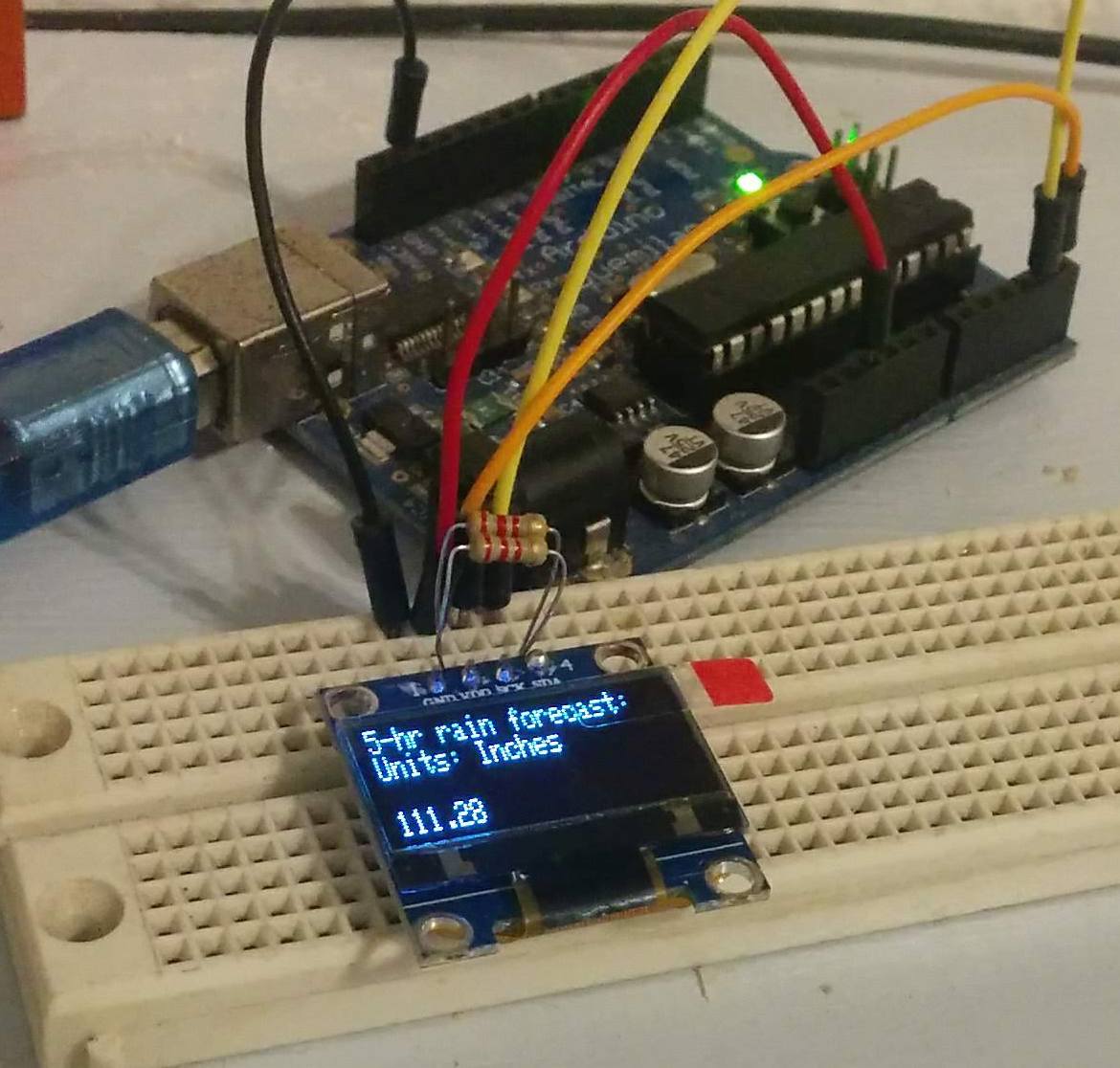
To interface with the OLED display I purchased, I found this library on Github. I found it straightforward to get started, even including an example application
As I mentioned in my prior article, the pin indication on these modules is actually wrong if you have one like this one. The real pins are shown in this table
| Label | Actual | Description |
|---|---|---|
| GND | GND | Ground |
| VDD | VDD | Positive voltage rail |
| SCK | SCL | Serial Clock |
| SDA | SDA | Serial Data |
This library implements a simple frame buffer in memory. All drawing is done by first updating the frame buffer then sending the updated pixels to the OLED. The downside to this approach is that the library consumes quite a large amount of memory, 1-bit-per pixel in fact. In my case this worked out to be 1 kilobyte of memory. This is half of the available SRAM on the microcontroller.
My use case is simple, I just need to output several rows of text showing the status of the thermostat. The first line is the set temperature, the system mode, and if the system is currently running. To show if the system is running I just chose to display AC when the air conditioning is enabled and AC* when the thermostat has actually turned on the air conditioning. The next three rows are just the three temperature data points I am collecting from the sensors. The thermostat only actually uses the ambient air temperaturefor control.
The last thing I realized was that since this screen is an OLED screen, it is likely to exhibit burn in. A thermostat displays the same thing all the time so this would happen pretty much immediately. High end displays solve this problem by having an extra row of pixels and shifting the image back and forth. This isn't really perceptible since a single pixel is such a small amount of movement on a modern screen. This cheap OLED doesn't have that kind of pixel density. But since the text I am displaying is smaller than the available screen space, I was able to program in a simple screensaver. Periodically the displayed text is shifted in the X & Y axis on the screen. It also resets back to (0,0) (the top left corner) as well. This should hopefully delay burn in to beyond the useful life of this device.
One of the most iconic features of computing systems has been the progress bar. This graphical element was first described in 1979 and I wanted to add it to my thermostat. So what I did was whenever the thermostat turns on the AC, it puts up an empty progress bar on the screen. As the house cools down towards the target temperature the progress bar fills up. This is actually pretty useful as on the hottest of days it can take a long time for the system to cool down the house. This simple grpahical element is missing from most cheap thermostats, although it would hardly cost anything to add.
Memory corruption
Since a thermostat is an always-on device I quickly noticed some strange behavior. It seemed that after running for long enough, the display library would just throw garbage on the screen. After double checking all of my code, I decided the bug had to be somewhere else. The image displayed on the screen was a weird mix of garbage and my intended text. I noticed that what should be showing a temperature was showing values like "255.0 F" which is obviously an invalid reading. This lead me to conclude that something was writing nonsense values into the microcontroller memory.
The pixel buffer used by the LCD library is just a large array in memory. Any error in writing to the array could easily result in corruption of the microcontroller memory. I searched through the library and eventually found that there is in fact bounds checking before writing to the pixel buffer.
However, I discovered this seemingly benign codepath
void GLCD_GotoY(const uint8_t Y)
{
    if (__GLCD.Y < __GLCD_Screen_Height)
        __GLCD.Y = Y;
}
The objective of this function was to check that the arguement Y is within bounds. Instead, it was checking __GLCD.Y which is actually the current screen position in pixels. This meant that it was possible to update the current screen position to something "off the screen" which is in fact just the rest of the microcontroller memory. I reported this issue to the author on Github and it was quickly resolved. After this fix, this was the end of my memory corruption problems.
Porting FreeModbus to the Atmega328PB
Previously I had discussed adding an RS485 transceiver. To make use of this communication hardware, I need some sort of software standard for communication. I contemplated developing my own standard, but realized I might actually want to complete this project sometime before I die. So I decided to pick the most commonly used industrial control protocol, Modbus. Modbus can technically run over almost any communication layer, but it is pretty popular to use over RS485 due to its low cost.
I surveyed what I could find in terms of open source Modbus implementations and eventually settled on https://www.embedded-solutions.at/en/freemodbus/. While there exists decent function level documentation as to what the library does, there wasn't really anything out there explaining how to use it on an Atmega CPU. I dug around in the provided .zip file and found a folder at the path demo/AVR. Oddly enough, this doesn't just contain a demo. It is a complete working implementation that works on many different Atmega chips.
Unfortunately this did not support the Atmega328PB yet. I discovered that I could edit the port.h file and add in support. The Atmega328PB is sort of unique because it supports two hardware UARTs. So I opted to use the second hardware UART in my case. The file port.h just defines a bunch of aliases that map #defines to actual values provided in the headers for the specific microcontroller you are using. This got me most of the way to a working system. Basically all the files in this demo directory are AVR specific implementations of functionality that is needed by the main library. This allows the main library to platform independent.
RE/DE support
The next step I needed was something called RE/DE support which is short for Receiver Enable/Driver Output Enable. Since I am using a half-duplex bus, the RS485 hardware has to switch between transmitting and receiving. It is normally left in the receiving state, so that commands can be received. Once a reply is ready to be sent, the microcontroller needs to toggle two pins on the RS485 transceiver. Those pins are labelled "RE" and "DE". Due to the electrical implementation these are simply wired together in almost all applications. Hence the term RE/DE. I figured the library already supported toggling this pin, but it apparently did not.
I eventually determined the function vMBPortSerialEnable is called with two values indicating if RX & TX should be enabled. By checking the value of the transmit enable flag I can know when to toggle the pin to put the RS485 transceiver in the transmit state. At some point the transmission is done and this pin needs to go back to a low state. This actually happens in an interrupt that is called by the microcontroller called SIG_UART_TRANS. So basically the following happens in the FreeMODBUS library
- A control message is received
- The library figures out the response
- The response is ready to be sent and
vMBPortSerialEnableis called withtxEnableset to true - The library feeds data to the hardware UART in the
SIG_UART_DATAinterrupt, one byte at a time - The
SIG_UART_TRANSinterrupt is called when data is done being transmitted
Responding to Modbus control messages
The FreeMODBUS library just implements a software interface to the Modbus standard. It doesn't actually know what you want to do when associated messages are received. In order to allow you to implement whatever behavior you would like, the library invokes callbacks. Each callback corresponds to one of the data types supported by the Modbus protocol. I'm not going to provide a complete guide on this here, but here is a brief example
eMBErrorCode
eMBRegCoilsCB( UCHAR * pucRegBuffer, USHORT usAddress, USHORT usNCoils,
               eMBRegisterMode eMode )
{
   // Your implementation goes here
This callback is invoked both for reading and writing of coils. The value usAddress indicates the first coil and usNCoils indicates the number of coils. It's up to you to decide if this range is valid or not. If the operation indicated by eMode is a write, you have to unpack the bits in pucRegBuffer to get each value. If the operation is a read, you have to pack bits into pucRegBuffer to set the correct value for each coil. There is a complete example here.
Once all the callback are implemented, you still need to tell the configure the library and tell it to start. This is done by calling the following functions
eMBInit( MB_RTU, 13, 0, 9600, MB_PAR_ODD );
eMBEnable();
The parameters passed into the function dictate how the library is being setup. This table shows what those parameters are
| Name | Example Value | Description |
|---|---|---|
| Modbus layer | MB_RTU | This is always RTU if you're using RS485 |
| Slave address | 13 | This is the Modbus slave address, any number 1-255 |
| Port | 0 | This is the port, its ignored in AVR port of FreeModBUS |
| Data Rate | 9600 | The serial data rate |
| Parity | MB_PAR_ODD | The type of serial parity to use, if any. I always use odd parity |
Once you've done all this, you need to incorporate the eMBPoll function into your applications main loop like this
while(1){
  eMBPoll();
  // Do your application work here...
}
Calling eMBPoll allows the library a chance to do any work it needs to. I didn't dig into the implementation, but it appears this call returns pretty quickly even when sending & receiving messages.
Testing my implementation
So now that I have a (theoretically) working embedded Modbus implementation, I needed to prove it works. So I found the utility mbpoll. I couldn't find this in any repositories, but managed to compile it myself. This tool is really great. After connecting a USB <-> RS485 adapter, I was able to quickly interrogate devices.
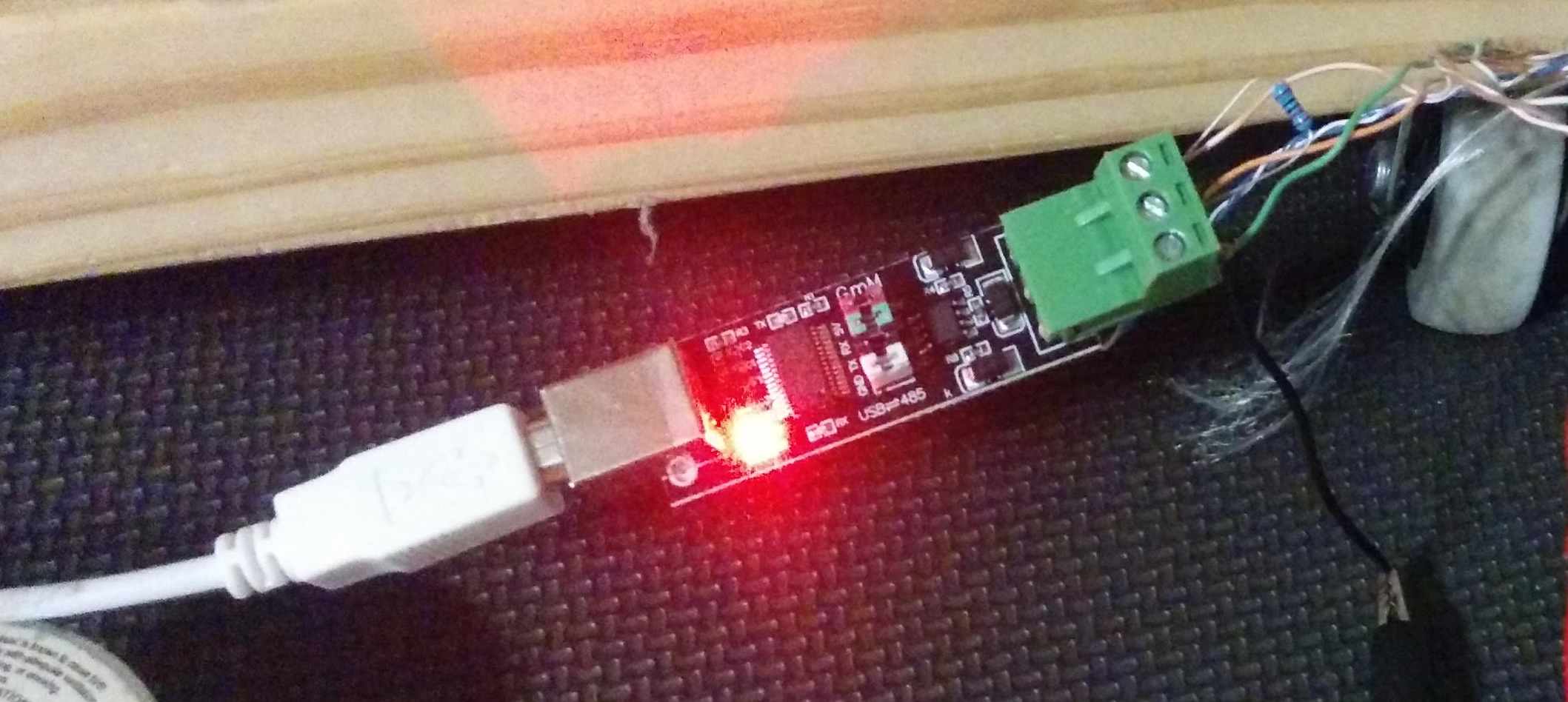
This cheap device connects via USB and looks like a serial port. It provides a half-duplex RS485 connection
The mbpoll program just takes a bunch of command line switches to specify what you would like to read or write and then shows the results in the terminal. This saved me lots of time while testing my port of FreeMODBUS because I could quickly try out different operations without having to write any code.
Interrupt contention
After getting the Modbus library working, I noticed a really strange problem. If I left the thermostat idle it would work indefinitely. If I used mbpoll to read the temperature once a second, it would work but eventually have to be reset. If I used mbpoll to read once every 300 milliseconds, the thermostat would die almost immediately. By "die" I mean it would stop getting new updates from the temperature sensors and I would stop getting responses as displayed by mbpoll.
This took me quite a while to understand, but since the library that reads the temperature sensors uses bit-banging it is very timing sensitive. Any interruption when it is called can lead to it either not sending the correct bits down the wire or missing the bits send in response. To think about it simply, anything that could cause the microcontroller to "blink" while interacting with the temperature sensors could screw the whole thing up.
This "blink" was happening because the FreeMODBUS library sets up lots of interrupts to fire when transmitting data data. This meant that polling the thermostat could lead to a failure in this timing. If you poll it fast enough, this would happen almost immediately.
The actual time it takes to transmit a response is minimal. As a result, I came up with this very simple "fix" for the problem
// Run if the UART isn't transmitting
if( 0 == (UCSR1B & _BV(TXCIE1))){
  ds18b20_poll_all(); // service all sensors
}
By checking the bit TXCIE1 in the UCSR1B register I can see if the interrupt for transmitting serial data is currently enabled. If it is, I don't bother polling the sensors. This obviously lowers the resolution of my temperature measurements, but it is not really detrimental to solving the problem.
Debouncing the buttons
One of the software components I had to implement that I hadn't previously done is switch debouncing. Mechanical switches don't work anything like nice software components such as HTML form buttons. Inside each switch is a set of metal contacts that are usually spring loaded. Whenever the switch is pressed, the contacts touch and complete the electrical circuit. However, the contacts also "bounce". This means the circuit is closed and opened very rapidly. This happens very fast, but not so fast that the 16 MHz microcontroller can't observe it. If you don't take this into account then each physical button press can get registered as multiple button presses.
You can electrically view this behavior with an oscilloscope. This instrument measures voltage over time. This is an example capture from my oscilloscope while pressing a button
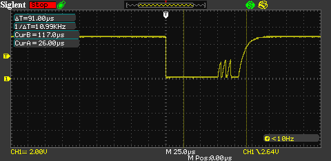
In the horizontal axis is time, and in the vertical axis is voltage. The voltage starts out at 5 volts and goes to 0 volts when the button is pressed. When the button is released the contacts "bounce" and create 3 small shark-fin looking voltage spikes before voltage settles back to the full 5 volts. The shark fins don't reach 5 volts, but the microcontroller isn't looking for exactly 5 volts to determine what constitutes a 1 bit in the port. There is actually a good deal of physics theory to it, but microcontrollers basically just have some threshold voltage above which they measure that the input pin is a bit value of 1. Each one of these shark fins can wind up triggering a false button press if the input isn't properly debounced. All 3 of these shark fins happen within 25 microseconds or about 400 cycles of the microcontroller running at 16 MHz.
The connection from the button to the microcontroller just goes to one of the digital I/O pins on the Atmega328PB microcontroller. So checking the state of any pin is just done by checking the present value of the appropriate PORT, in my case PORTB. The obvious implementation is something like
if (0 != (PORTB & buttonPin){
  do_something();
}
This usually detects the button press, but if this is run in a loop it almost always get multiple detected presses when a single physical press occurs. The obvious way to prevent this is something like this
if (0 != (PORTB & buttonPin){
  do_something();
  _delay_ms(200);
}
Adding a delay of 200 milliseconds usually is long enough for the button bounces to end. But this assumes that the user immediately releases the button which of course isn't true. If they hold the button down for a while the bounces would come later. Properly handling this sort of thing is a topic unto itself. If you're interesting in learning more then A Guide to Debouncing is the correct place to start. I wound up using a modified version of the procedure DebounceSwitch3 described on page 21.
Choosing cycle limits
One problem I had no idea how to approach is setting cycle limits. The system should obviously run until the target temperature is reached. But such a simple approach would be no different than most mechanical thermostats.
After some amount of experimentation I decided to program in a miminum cycle time of 11.5 minutes, with a minimum off time of 3.5 minutes. What I observed was that on a typical day, 11.5 minutes of run time would reduce the indoor air temperature from around 75 F to 72.5 F. I consider this an acceptable amount of temperature swing. The minimum cycle time becomes less of an issue as the days get warmer in the summertime because the system simply has to run longer and longer to keep the house cool. The same would be true if you kept the thermostat set on a very low temperature like 69 F.
The same minimum cycle times are applied to furnace operation, but I don't much care about that. Our winters are very mild and I rarely run the central heat anyways.
The control loop
On the Atmega microcontroller I am not using any sort of operating system. The control of everything consists of just a single loop. That loop does the following
- Check the 1 second interval timer, run the low frequency loop
- Debounce all switches
- Run
eMBPollto check for Modbus activity - Update the flag if the display is set
The "low frequency loop" from step 1 is a list of activities that are checked only when the timer has fired. Those things are
- Mark the display to be updated
- Increment the number of times the timer has fired
- Check all the sensors, if the UART is not sending data for Modbus
- Decrement the system change delay counter, if above zero
- Decrement eeprom update counter if, above zero
- Check the climate control system and update the state if needed
- Invert the LED that is onboard the Arduino board
- Reset the watchdog timer
This implementation turned out to have lots of advantages. First of, there isn't any reason to check the sensors more than once a second. But primarily step 7 was very helpful. Since the LED is inverted each time this loop runs, it blinks once a second. Whenever I was debugging issues, if the LED stopped blinking I knew that the something had went awry.
Steps 4 and 5 are a simple way to implement delayed actions. Since I didn't want to update the EEPROM every time the set temperature on the thermostat changes, I just start a timer by incrementing a value to non-zero number. If the loop ever decrements the counter to zero, it goes ahead updates the values stored in the EEPROM.
Watchdog timer usage
One of the functions of the main loop of the software is to reset the watchdog timer. The watchdog timer is a hardware function of the Atmega microcontroller. It's basically a timer, that if it ever reaches zero resets the microcontroller. To reset the watchdog timer, the pseudo-function wdt_reset() is used. The interval is configurable to a number of predefined values.
This is useful because if the software has a bug that prevents the loop from continuing to run the watchdog timer eventually takes over. At this point the microcontroller is just reset. This isn't ideal behavior, but it means that at least you don't have to power cycle the microcontroller to get it working again.
The biggest obstacle I had with using the watch dog timer was it seemed that the microcontroller would just wind up in an reset loop once the watchdog timer was hit. After doing some research, I found out the bootloader has to properly clear some flags when the microcontroller starts up. Optiboot does this, but only in newer versions. I don't know what version was loaded onto the microcontroller when I got it, but after programming the latest version of Optiboot everything started working. There is no official Optiboot for the Atmega328PB, but the version for the Atemga328P works due to the similarity in the two parts.
An example of this is shown below, with comments
:: c

int main(void){
  wdt_reset(); // Clear the watchdog
  wdt_enable(WDTO_1S); // Set the watchdog to 1 second

  // loop forever
  for(;;) {
    wdt_reset();
    do_work(); // if this does not return within 1 second the WDT resets the microcontroller
  }
}