Using the Atomic Pi as a workbench computer
Having previously looked at the Atomic Pi I decided the best use for it was to act as a computer to have on my workbench. Currently I was using a Raspberry Model 3B+ which worked, but only having 1 GB of RAM was a little annoying. The Atomic Pi was mostly a "this looks interesting" purchase, so using it as a second desktop seemed like a logical purpose for it.
Housing the Atomic Pi
The Atomic Pi isn't really a mass-produced part, as a result I doubt anyone is going to commercially produce cases for it. So my only really option was to make one. So I jumped into OpenSCAD and started modelling something I could 3D print myself.
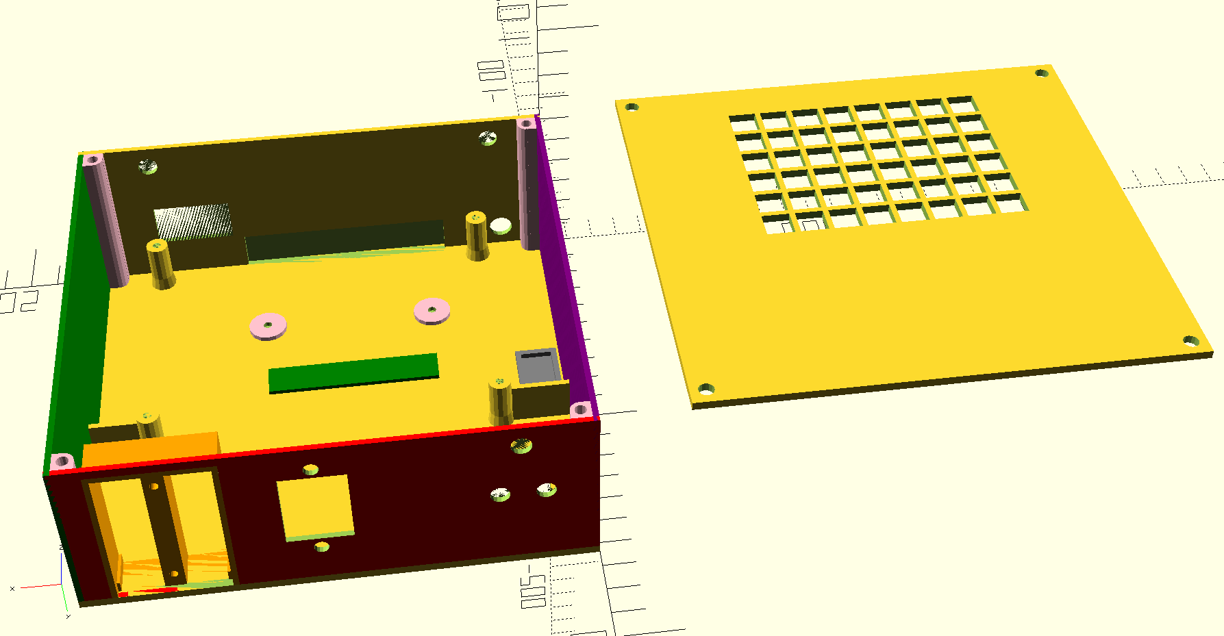
Creating this took longer than expected, but packs everything into a small space
This case allows me to put all the following into a single housing
- The Atomic Pi board
- 2.5 inch SSD
- USB3.0 to SATA adapter
- 5 Volt buck converter
- Power switches
- Antennas for Bluetooth & WiFi
- An Arduino Nano
Most of the above is self explanatory. In order to fit a full 2.5 SSD, I created a little pocket on the backside to avoid making the case take way too long to print. There is a cap that is glued onto this section, it was printed as a separate part. In order to make sure that heat can escape, I put a grill in one side of the case and in the top. All cooling is passive with this design, I decided not to try and add fans.
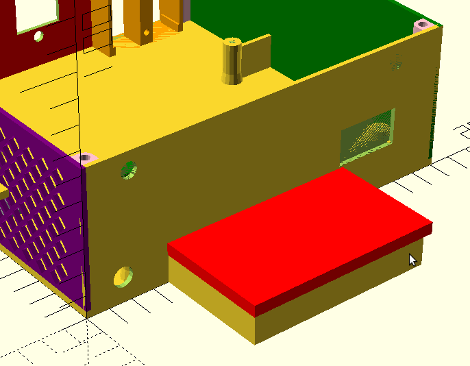
The backside complete with a pocket to allow the SSD to fit
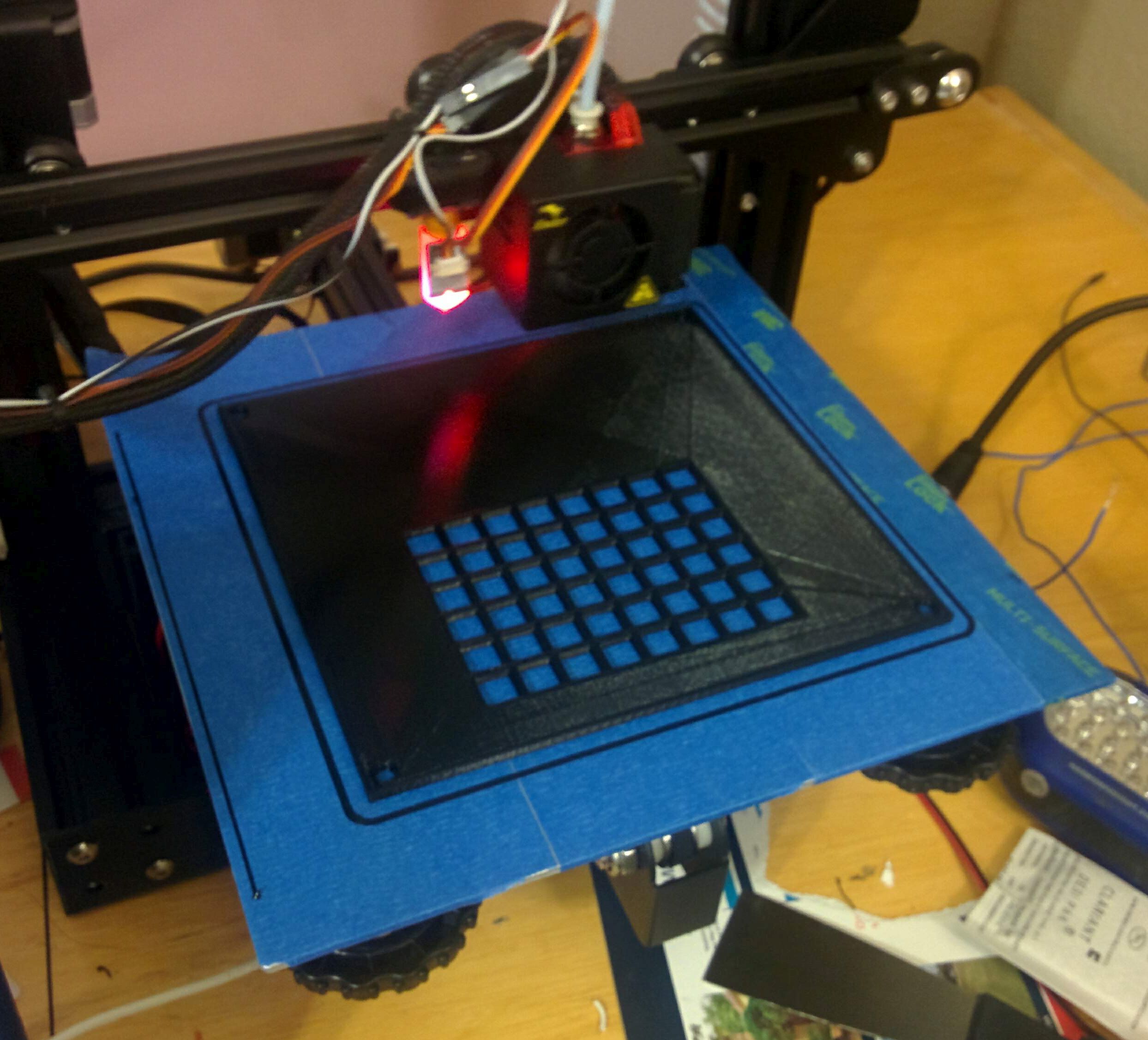
The entire case was 3D printed taking about 20 hours. Shown here is the top
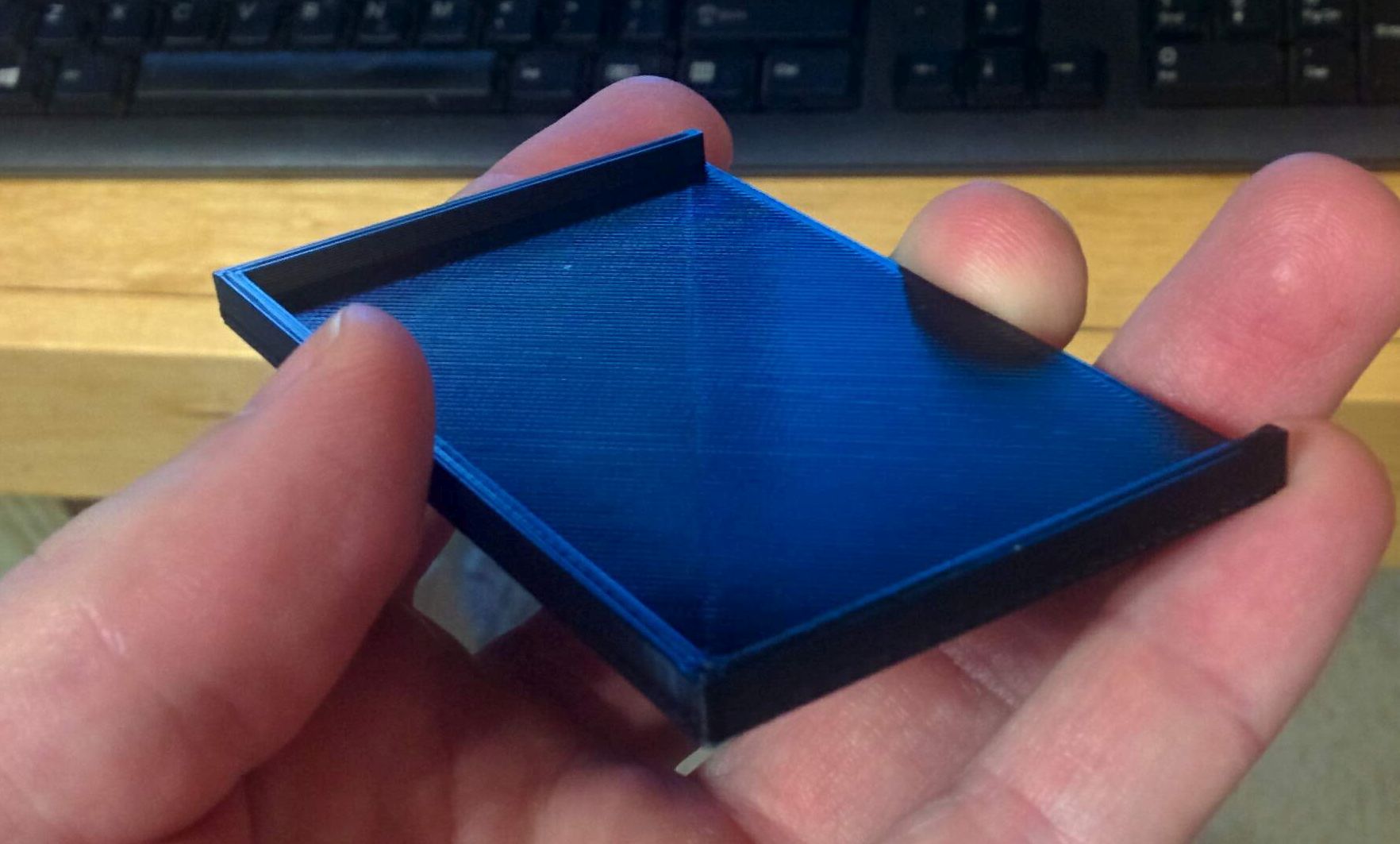
This small part was printed separately and glued on
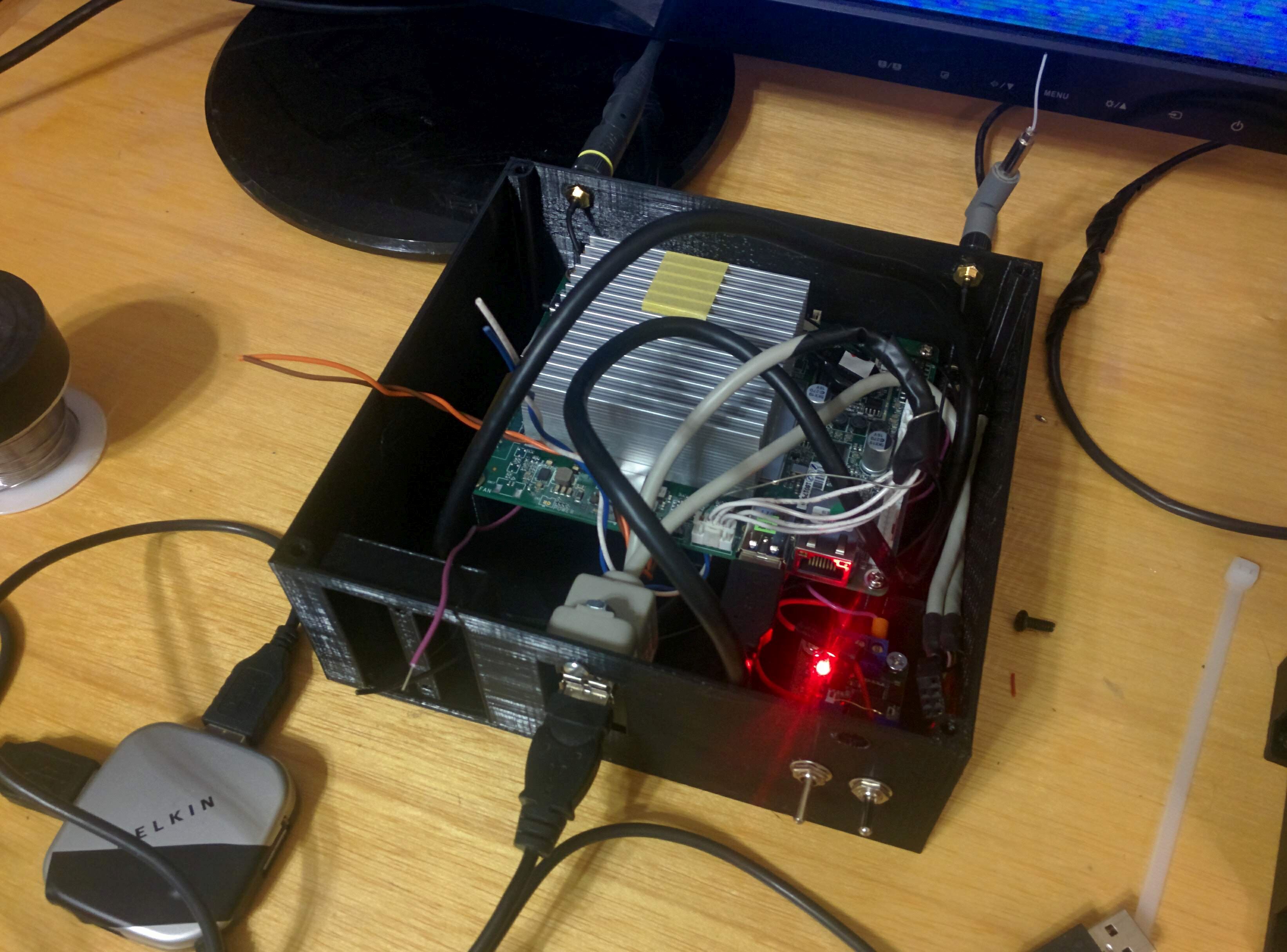
The wiring on this is less than neat, but I can live with that
Getting another USB port
I chose to use the USB 3.0 port to connect to an SSD via a SATA adapter. This leaves only Bluetooth for basic connectivity, which I did not really want to use. Since the original article I published about the Atomic Pi I found out the "WEBCAM" port is just another USB port with an extra pin. I rummaged around in my junk box and found a panel mount USB connector in addition to the matching connector to the one on the Atomic Pi board.
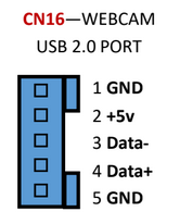
This gives me a single USB port that I can connect a hub to with my peripherals.
Power & Connectivity
As I explained in the previous article, the power header is on the bottom of the board. In order to connect to this I created an adapter using a piece of perforated circuit board. On this I added a connection for 5 Volts DC and ground. I also put a level converter on this. The converter is bidirectional with 4 channels with a 10k Ohm input impedance. The purpose of this part is to allow the 3.3 volt level used for IO by the Atomic Pi to interface with the 5 volts used by the Arduino. I connected two of them to GPIO ports and the other two to a UART. One issue with this is I could not find anywhere convenient to get a +3.3VDC connection on the Atomic Pi. This is needed to hook up the bidirectional level converter. However, the Arduino Nano I added to this setup has a +3.3VDC voltage source onboard. So I just ran the wire over to that, which should work fine.
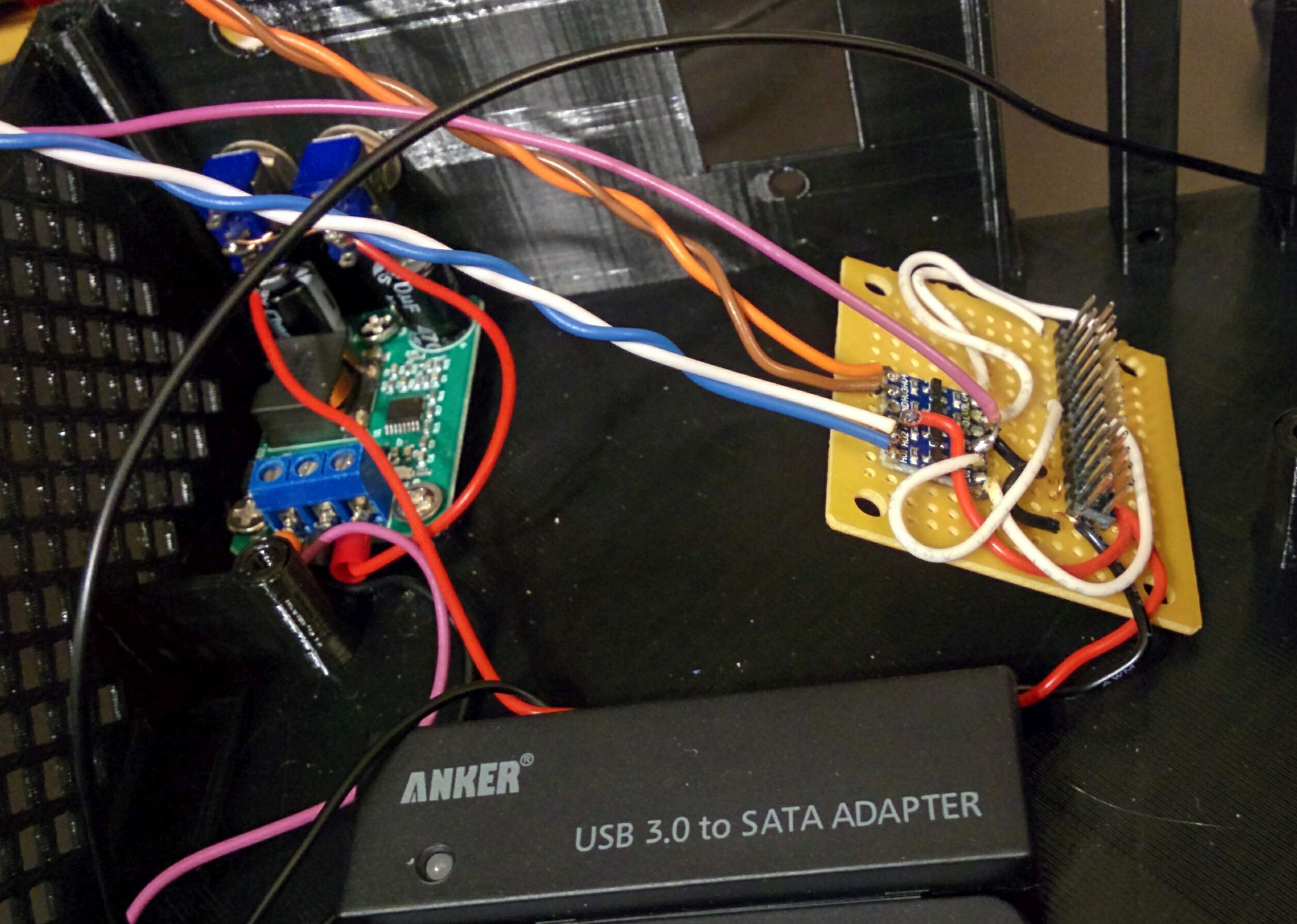
All of this is on the same header on the bottom. So I just plugged this in before mounting the board and it will probably never be seen again.
The internal buck converter just regulates DC power down to 5 Volts at up to 5 amps. The actual power for this device is supplied by a 24 volt DC 1 amp wall adapter. There is a barrel connector on the back that it connects to.
Adding an Arduino
Since this computer is going on my electronics workbench I decided I wanted to merge an Arduino Nano into this project. The idea behind this is I can just use the Arduino Nano as a GPIO expander attached to the Atomic Pi. Control of the Arduino can be done over serial with the onboard UART. Mainly I just want a way I can have some software running on the Atomic Pi be able to to flip pins on the Arduino low or high for output purposes. I assumed someone would have come up with a standard sketch for this, but I didn't find anything. So programming that will have to wait for later. If I want to data acquisition I did find the Girino Project but it is honestly probably overkill for what I need. If I actually need to measure waveforms, I have a digital oscilloscope on my bench I can use.
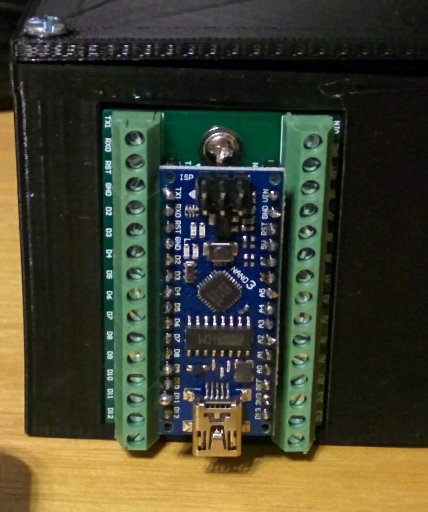
In order to mount the Arduino I used a breakout board specifically designed for being mounted. The 3D printed case has a hole in it that is the exact dimensions of this breakout board. I also didn't want a bunch of wires coming out the front only to go back in the case. So my solution to that was to solder onto the backside of the breakout board before mounting it
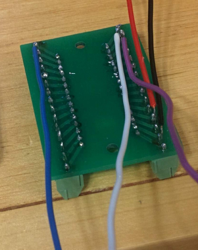
This provides connections to +5 Volts, +3.3 Volts, Ground, Arduino Pin 12, & Arduino Pin 13. The last two pins are probaly going to be used for software serial in order to communicate with the Atomic Pi.
The real advantage to this setup is not only does this give me more pins to act as GPIO, it protects the Atomic Pi. If I do something foolish like accidentally put +12 VDC into one of the output pins from the Arduino I will have only killed the Arduino. These boards cost about $1 on AliExpress. This is cheaper and easier to replace than the Atomic Pi.
The finished product
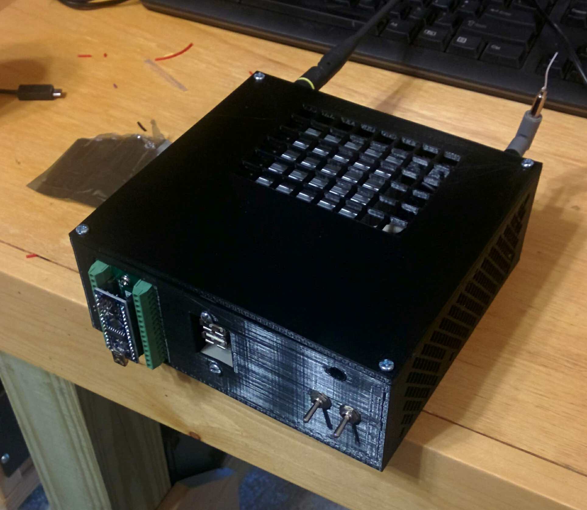
So this is what everything looks like when assembled. The switches on the front turn the Atomic Pi and Arduino Nano on and off independent of each other. Unfortunately my 3D printer is not perfect and there is some distortion as the prints get taller. As a result, the lid doesn't have exactly the same dimensions as the top of the box. So I had to flex the top a bit to get the screws into it. But it still works fine and the total cost of this case is under $5 of material. With the housing solved there were a few more software changes I had to make.
3D printing files
If you'd like to print this case, you can download this ZIP file with all the STL files inside. Keep in mind, things like the USB port I mounted to the front panel were just random junk I had laying around. So you may not be able to source it. The buck converter is commonly available on AliExpress.
Software reconfiguration
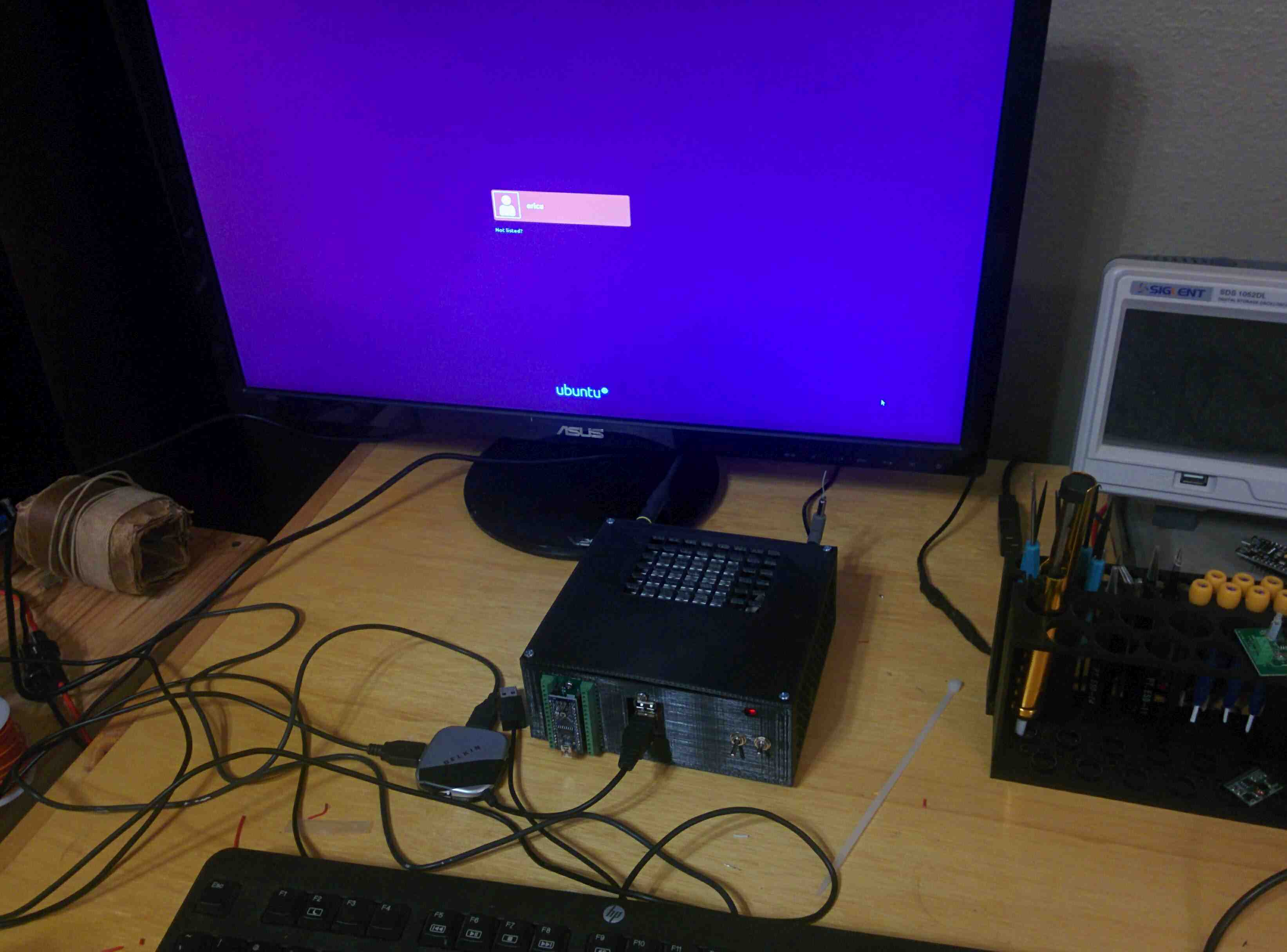
I had already setup Ubuntu 18.04, but wanted to make some additional changes.
Goodbye Gnome
I'm not much of a fan of Gnome in the first place, and Ubuntu ships with a display server other than X11. However, the ability to easily extend graphical applications over SSH is one thing I definitely I can't live without. So my first order of business was to re-enable X11.
If you open /etc/gdm3/custom.conf as root you'll find a line looks like this
#WaylandEnable=false
This line is just commented out, to put it into effect just remove the leading # so it looks like this
WaylandEnable=false
This information is taken from here. With X11 re-enabled, the only remaining step is to install Xubuntu desktop. This is done by running the following command
sudo apt-get install xubuntu-desktop
After that you can restart and then select "XFCE" as the desktop option at the login screen. XFCE is slightly less resource hungry than Gnome, but I personally find it much more usable.
Getting the WiFi to work
So at this point my system was mostly functional. With the antennas I added I was able to get a good reported signal from wireless access point. However, I was still plagued with poor throughput and high latency over my wireless connection. A simple ping was taking up to 1000 milliseconds to get a reply! My Raspberry Pi had worked fine from this same location, so I was pretty confused.
It turns out, the onboard WiFi of the Atomic Pi is actually connected via USB despite being onboard. It uses the rt2800usb driver in the Linux kernel. Overall this doesn't really mean much, but apparently it supports hardware encryption which may be problematic.
Hardware encryption can be disabled by creating a file called /etc/modprobe.d/rt2800usb.conf and putting the follwoing in it
options rt2800usb nohwcrypt=1
After a restart, this change didn't do much. So I did some more looking and ran wlconfig to get some basic information about my connection. The output looks like this
wlx0007234e2a98  IEEE 802.11  ESSID:"xxx"
          Mode:Managed  Frequency:2.462 GHz  Access Point: AC:9E:17:XX:XX:XX
          Bit Rate=1 Mb/s   Tx-Power=20 dBm
          Retry short  long limit:2   RTS thr:off   Fragment thr:off
          Power Management:on
          Link Quality=48/70  Signal level=-62 dBm
          Rx invalid nwid:0  Rx invalid crypt:0  Rx invalid frag:0
          Tx excessive retries:530  Invalid misc:268   Missed beacon:0
The reported link quality is 48/70 is actually very good. This means the Atomic Pi can "hear" the access point without any problem. But in the suburban setting I am in, there is a huge number of competing sginals. The other line saying Tx excessive retries:530 turns out to explain the problem. What this means is in order to get my access point to hear the Atomic Pi, the Atomic Pi is having to retransmit packet over and over again. This is bad and explains the high latency I was seeing.
At this point I thought I was stumped because the wlconfig output was reporting also reporting Tx-Power=20 dBm. This is the transmit power of the Atomic Pi. A transmit power of 20 dBm is actually incredibly powerful. But it turns out there is one last thing: power management.
In order to disable power management I opened the file /etc/NetworkManager/conf.d/default-wifi-powersave-on.conf and edited it to look like this
[connection]
wifi.powersave = 2
Setting a value of 2 for wifi.powersave permanently disables power management for all WiFi devices. After a reboot, this change was successful! Everything worked as expected now. I don't really know what power management means in the context of a WiFi adapter, but it must somehow affect the transmit power even if the reported power by the adapter is very high.