3D printing from a software developer's perspective
I recently purchased a Creality branded 3D Printer from BangGood. This is my perspective on the software stack I used to get up and running with the printer. There are far more pieces of software than I could ever find time to try, but this is what worked for me.
How the software stack works
To go from an idea to an actual printed part, you must use more than one piece of software. This graphic roughly shows how that works.
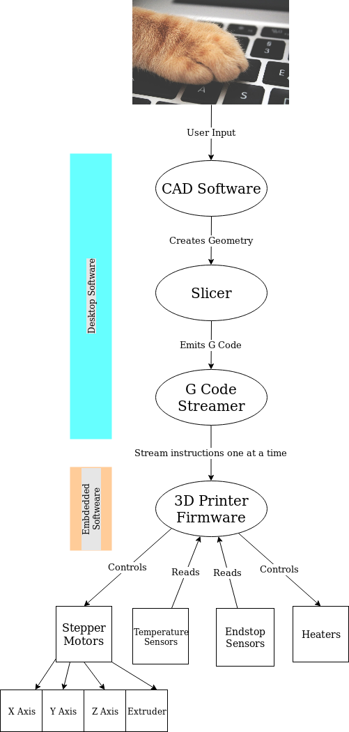
The overall software stack is split between things you need to run on your desktop computer and software that runs on an embedded microcontroller. If the 3D Printing revolution was happening 20 years ago, it is likely that everything would run on your desktop computer. But with the rise cheap, relatively powerful microcontrollers it makes much more sense to simply embed into the printer a microcontroller for doing all the work of actually running the thing. This is actually a much more robust design in my opinion. It is much easier to guarantee strict timing of software execution on a microcontroller than on a PC running a desktop OS. This means that reacting to events like a motor hitting a physical endstop and power being cut can happen in a well defined time.
CAD Software
The first piece of software you'll need to design a part is some CAD software. Commercial and free options are plentiful. There are of course now web-based CAD tools which can run entirely in your browser. It's entirely possible to skip this step by just downloading a part that someone else took the time to define. For the first things I printed I just downloaded a file from Thingiverse that contained what I needed. If you choose to do this, be sure and carefully read the authors description of the part. Many author upload 3 or 4 different files that contain the same part, but with small variations. For pretty much everything you'll get an STL file that defines the parts geometry.
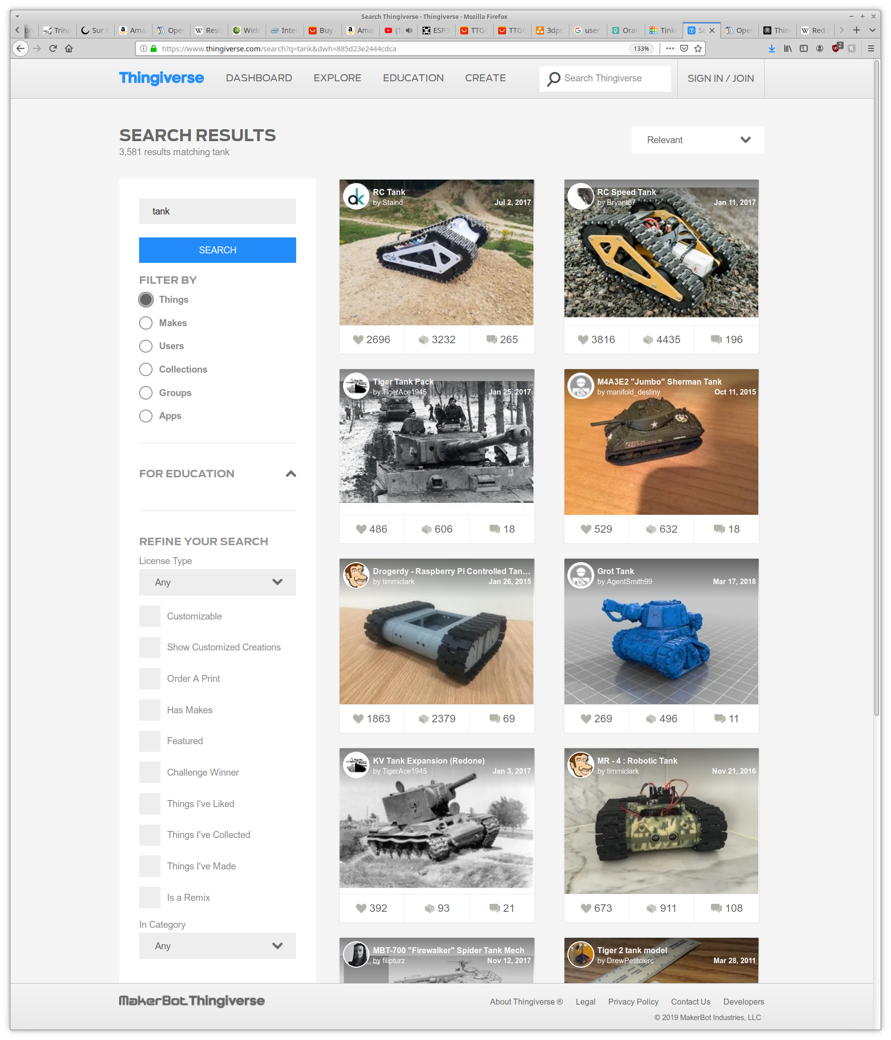
There are over 3000 results for 3D printed toy tanks
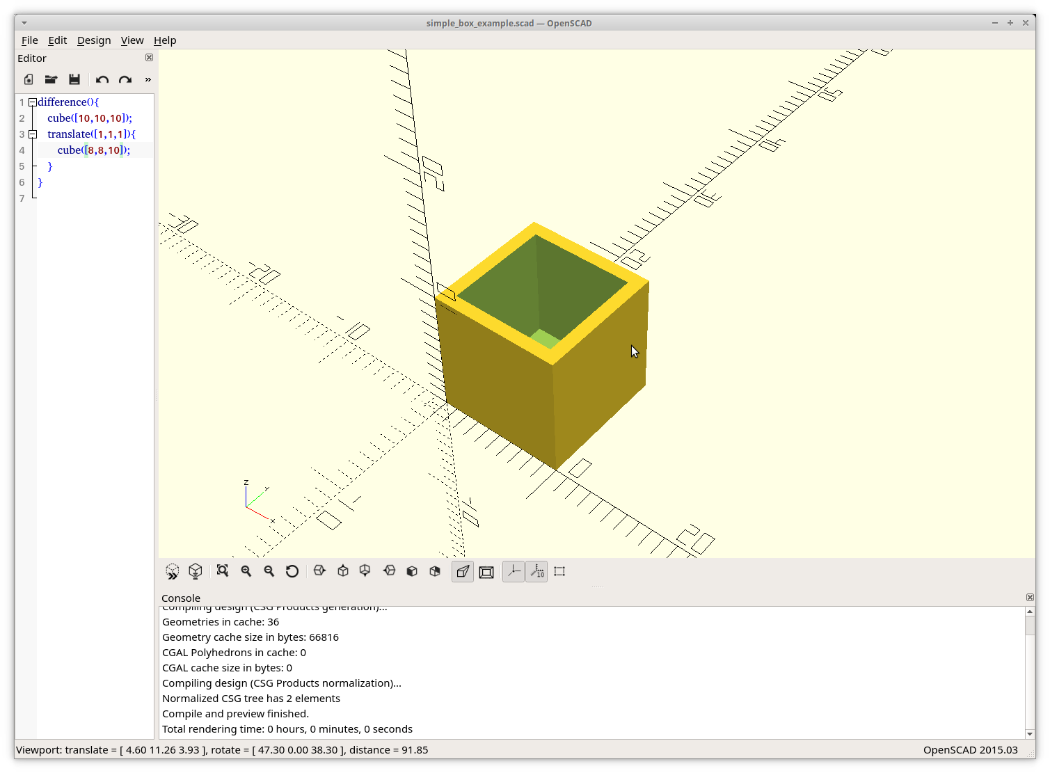
But eventually you'll want to create your own parts. I certainly did. I have always felt that using a mouse and keyboard to define a 3D structure is a clunky method of things. The only 3D editor I ever found easy to use was the one included with the video game Red Faction. It was very basic in what it allowed you to do and that was over 15 years ago. So I really was not looking forward to mastering a CAD tool when I really just needed to do simple things like "draw a box with 4 walls". I was pleasantly surprised to find out that a tool called OpenSCAD exists for people just like me. Want to create a 10x10x10 cube and print it? The only command you need is cube([10,10,10]). If you have ever written software before, you'll find OpenSCAD to be very familiar.
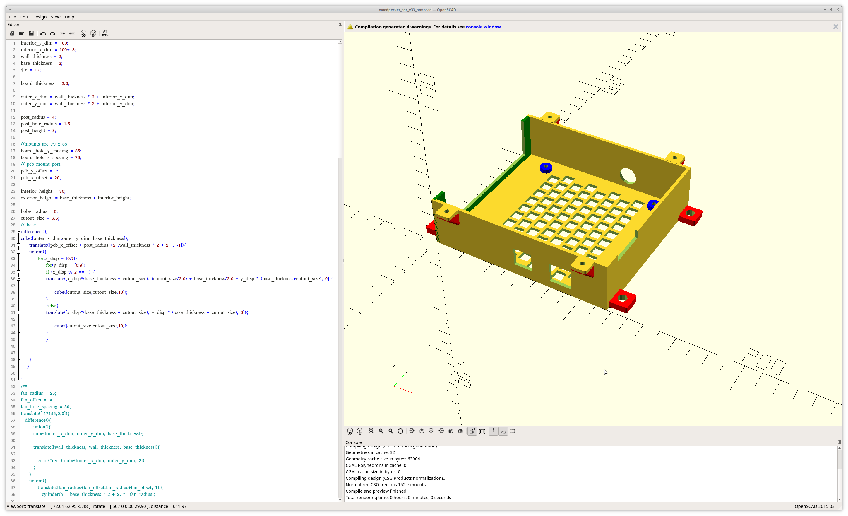
A simple circuit board mount I modelled in OpenSCAD
OpenSCAD has a simple user interface. On the left you put in text based commands that define what you want it to draw. On the right hand side, a 3D Model is rendered with the typical X-Y-Z axes. You can use your mouse to move around and zoom in on what you've created.
Defining 3D models really can be this simple
The language that OpenSCAD uses is unique to it. It is actually a purely functional programming language. However, you should not let that scare you away from it. This isn't Lisp and you aren't trying to create a piece of software that runs a website. The viewport on the right lets you get immediate feedback on what your code is doing. If you're code isn't perfect but creates the part you want, don't worry about it. You can always refine your skills on the next part you define. The complete language specification is very approachable, including both code examples and images showing what they create.
Once you've got your part created, you can press F6 to do a full render. Then you can export by using File -> Export on the menu. I always have exported to a STL file. You'll want to keep the .scad file that OpenSCAD saves everything as well in case you want to make modifications in the future. It isn't really practical to edit the generated STL.
Summary of OpenSCAD
Advantages
- Uses code to define geometry
- Editor allows for immediate feedback to code changes
- Low learning curve for simple parts, if you're already a developer
Disadvantages
- Not really suitable for artistic work
- Export can only define 1 part, so making a box with a top can require two OpenSCAD project files
Slicer and G-Code Streamer
Once you have your 3D Geometry defined, you'll need to import it into a piece of slicing software. Slicing software is responsible for converting the geometry into a structure that can actually be printed and then into a series of commands that actually tell the 3D Printer the exact moves to make. The slicer outputs something called G-Code. G-Code is roughly equivalent to assembly for 3D printers. It is actually used by all sorts of CNC machines, not just 3D printers. G-Code is actually a proper programming language, but the output of a slicer isn't really anything more than an explicit list of steps telling the machine things like "move 10mm to the right in the X-Axis", "turn on the extruder", or "heat the bed to 65 C". In some industries, G-Code is actually written directly. But for 3D printing tasks I have found it easy to stay away from, other than a few diagnostic tasks I learned.
One of the important things to understand here is that this process is not deterministic or in anyway exact. The easiest case to consider is the simple 10x10x10 cube. Do you really need a solid 10x10x10 cube of plastic? There are so many ways to print a simple cube. For example, consider the possible answers to the following simple questions
- Do you need a solid or do you just need something with those exterior dimensions?
- Could the interior be hollow?
- Does it need to be able to support some amount of weight placed upon the top of the cube?
Slicers are able to convert solid physical geometry into things that are practical to print. Slicers have a huge number of parameters that control how this process is done. You could of course attempt to print a solid cube, but it would take forever and may not come out the way you want.
In addition to creating voids in a part, a slicer can also add features like rafts and supports. Supports are pieces of printed material that allow discontinuous geometry to be printed. The fundamental problem here is that a 3D Printer can't print in midair, at least not until the problem of anti-gravity is sorted out. If you're willing to waste a small amount of material the slicer can print some very lightweight towers that allow things to printed above the bed. The towers are simply cut out of the finished part with a knife. I enabled this option for a few things I found on Thingiverse. Supports aren't always necessary, if you're trying to print for example a "top" to a box the printer can actually bridge a horizontal surface across two vertical surfaces surprisingly easily.
Rafts are large surfaces that are printed onto the bed before the actual part is printed. This is used to ensure good adhesion to the bed and attempt to address some other problems with 3D printing. I have not tried this feature yet.
I ended up using Ultimaker Cura for all my slicing needs. It is freely available from Ultimaker. It has a wide range of predefined machine profiles for commercially available machines, not just Ultimakers own products. The entire project is written in Python and uses the Uranium framework. It was very easy to get running on Linux as it comes distributed as an AppImage.
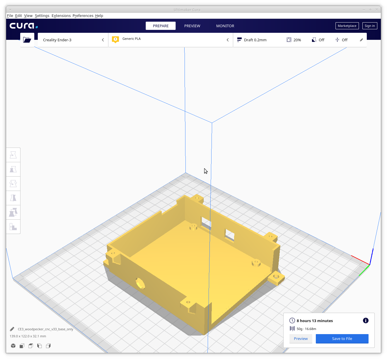
I was able to get to printing just a few minutes after installing Cura. Once I told it I had a Creality Ender 3, it automatically detected it was connected via USB and started communicating with it. Once you import an STL file, it is displayed on a virtual bed, where you can reposition it if needed. Cura allows you to import multiple STL files. So if you have lots of small parts that all can fit on your bed, you can print them all at once in a large batch.
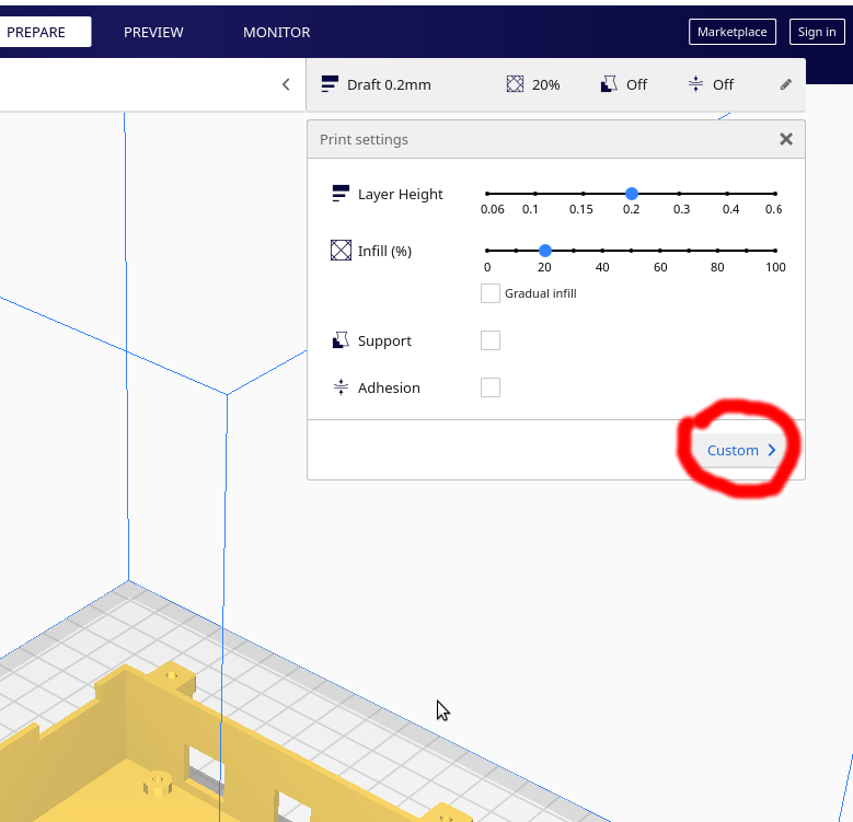
Cura has many parameters that you can adjust by clicking in the upper right hand side of the screen and then clicking "Custom". The actual list is huge, so I just use the search functionality to find what I need. I found adjusting the following parameters to be helpful:
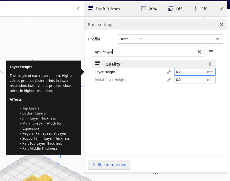
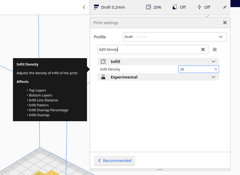
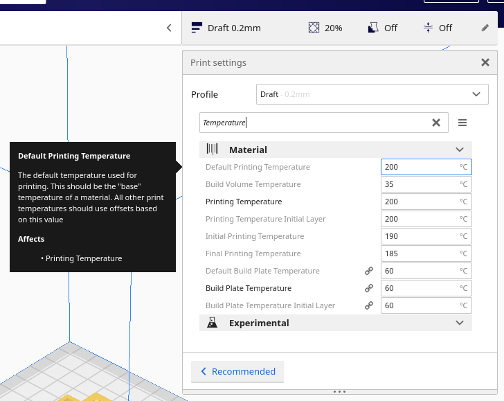
- Layer Height
- Infill Density
- Default Printing Temperature
The first option, layer height controls how many layers that your object gets sliced into. The larger this value is, the less number of layers you have to print to create the part. This seemed to be a straightforward way to reduce the print time. As this value becomes larger, the layers in the finished part become more and more visible. There are also physical limits to how small or large of a value you can use, but that varies by printer. I was able to increase this setting from 0.2mm to 0.3mm.
Infill density is how much filler needs to be put in solid parts. An infill of 100% would correlate to actually printing solid parts. I don't recommend this. The lower this percentage is, the faster the print is. It simply means less material needs to be printed. I have printed parts between 15% and 50% infill. The parts with 50% are very strong.
The final option I experimented with was "Default Printing Temperature". Cura has a bunch of printing temperature options, but apparently most only apply to 3D Printers with dual extruders. Changing this setting allows the temperature of the printed filament to be adjusted. The actual value needed here to get good quality prints varies from one filament spool to the next.
Once the slicer creates G-Code, it needs to be sent to the 3D Printer one instruction at a time. The actual number of instructions can be huge and a microcontroller does not have enough memory typically to store them all. It is possible to use an SD Card containing the G-Code to print without streaming the G-Code. Pretty much every slicer includes the option to stream G-Code and I found printing over USB to be more convenient.
Summary of Ultimaker Cura
Advantages
- Easy to use
- Simple interface for importing & arranging multiple parts
- All slicer settings can be customized
Disadvantages
- No way to troubleshoot communication errors with printer
- Doesn't preheat bed & extruder simultaneously, so prints take a long time to start
3D Printer firmware
With a complete set of G-Code instructions to print your part, the only remaining step is to actually get the machine to perform those steps. Like most of 3D Printing, there are plenty of options to chose from here. The firmware is responsible for taking G code instructions like "move 10mm to the right on the X Axis" and then actually making the stepper motors move the correct number of steps to get 10mm of movement.
Any commerical 3D Printer you purchase comes complete with some piece of onboard software to control all the motors, heaters, etc. Some printers may ship with proprietary software, but the Creality Ender 3 ships with the Marlin Firmware. The version that ships with the Creality Ender 3 is a very old version of Marlin. For reasons I'll elaborate on later I unexpectedly became an expert in the firmware options available. The Ender 3 is not the only 3D Printer to ship with open source firmware, plenty of other ones do as well.
The Creality Ender 3 ships with a simple control board that is based off an Atmega328P microprocessor. It is essentially an Arduino with an onboard set of stepper motor drivers. The problem with the Atmega328P is it does not have much code space available onboad the microcontroller. As a result, I never actually used the control board that shipped with it.
Instead I purchased a MKS Gen L version 1.0 board and installed the latest version of the Marlin firmware on it. This board is based of the Atmega2560 which has a larger code space. Compared to the rest of the software, this is the part that required the most work on my part. The process for doing a conversion like this roughly consists of
- Selecting a controller board
- Selecting stepper motor drivers
- Assembling the two together
- Connecting the assembled board to your 3D Printer
- Getting the latest version of Marlin
- Going through the massive
Configuration.hfile to change all the settings - Flashing it onto the board
This process involves not only software knowledge but skill connecting up an electrical system. If you're not comfortable doing basic electric wiring and editing C header files I would not recommend attempting this. To configure and compile Marlin you need to use either the Arduino toolchain or the Platform.io toolchain. I used Platform.io with the Visual Studio Code plugin.
I'm not going to list out all the configuration changes I made here, because setting up Marlin is probably worth of an article itself.
When it comes to firmware, it either works or it doesn't. In my case, I was able to get Marlin working pretty quickly. So I did not experiment with anything else. Marlin is in fact overflowing with features, I have barely used anything outside the basic feature set.
The Creality Ender 3
The Creality Ender 3 is my first 3D Printer purchase. I purchased it for only $180 from BangGood. It arrived well packed in a box with absolutely no damage. It comes with everything you need to assemble it, including some basic tools. I was able to get it assembled in about 2 hours of work. The basic design of the printer is just an open frame with only a single motor on each axis so it lends itself to quick assembly. I won't go into detail about assembly because there is no shortage of YouTube videos out there about this already.
Everything about the Ender 3 is incredibly simple and cheap. If you look around, there are countless "clones" of the machine selling in the range of 300-600 US dollars. Some do come with significant upgrades, but most seem to be identical. I can safely say that the Ender 3 is the best value for your money. But I must stress that it is far from a turnkey machine or a professional setup. To understand, keep reading the following sections.
The printing surface
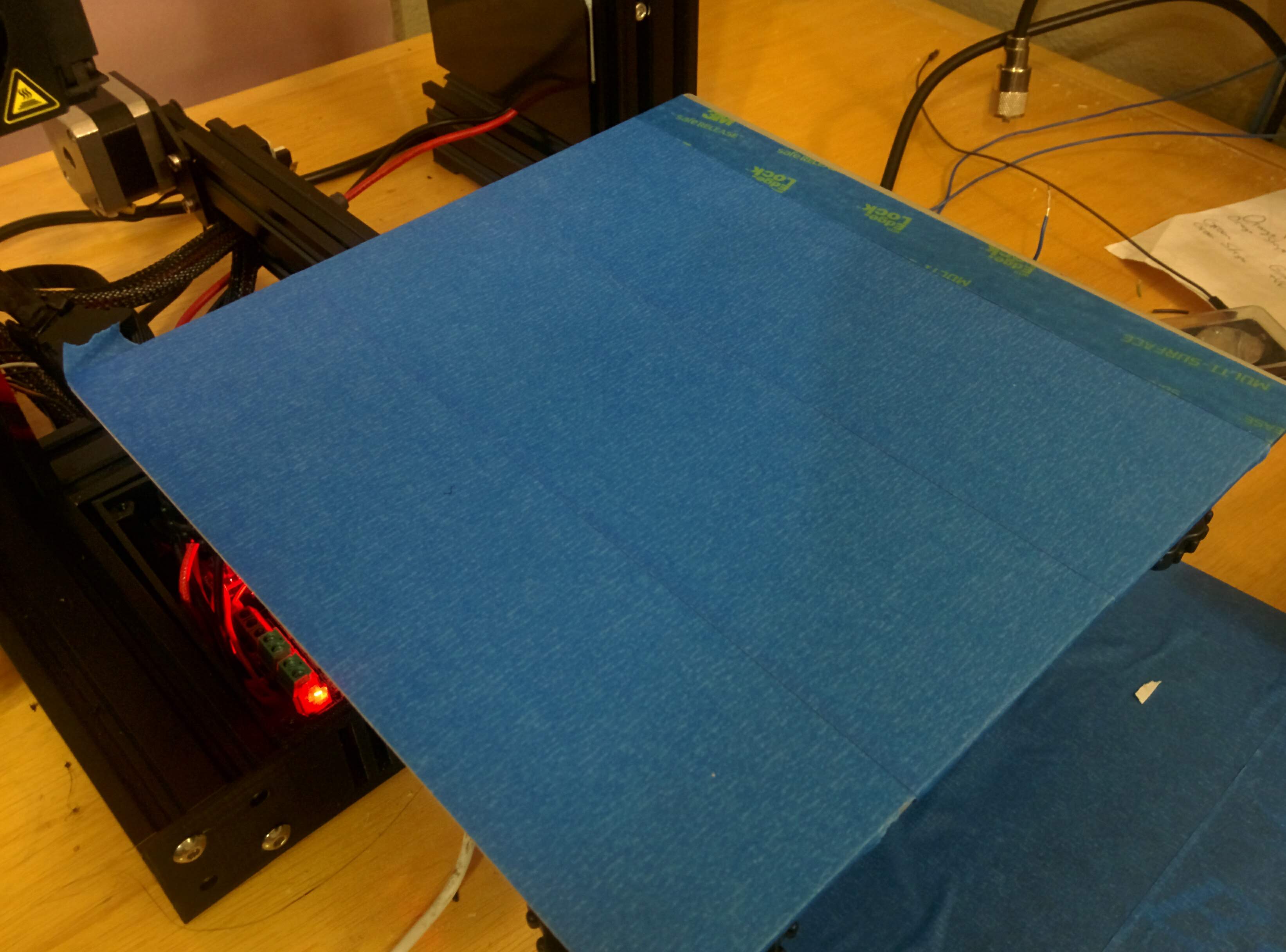
The Ender 3 comes with an interesting print surface that is designed to attach to the bed with 4 binder clips. I'm not entirely sure what it is made of, but it is highly textured. So the first layer of filament adheres to it very easily. But this surface is awful for a whole list of reasons:
- The first layer sticks so well it is hard to get parts off of it
- It has to be held on with binder clips, which interfere with the print area
- When heated, it seems to warp upwards into a slight bowl shape. This distorts your print.
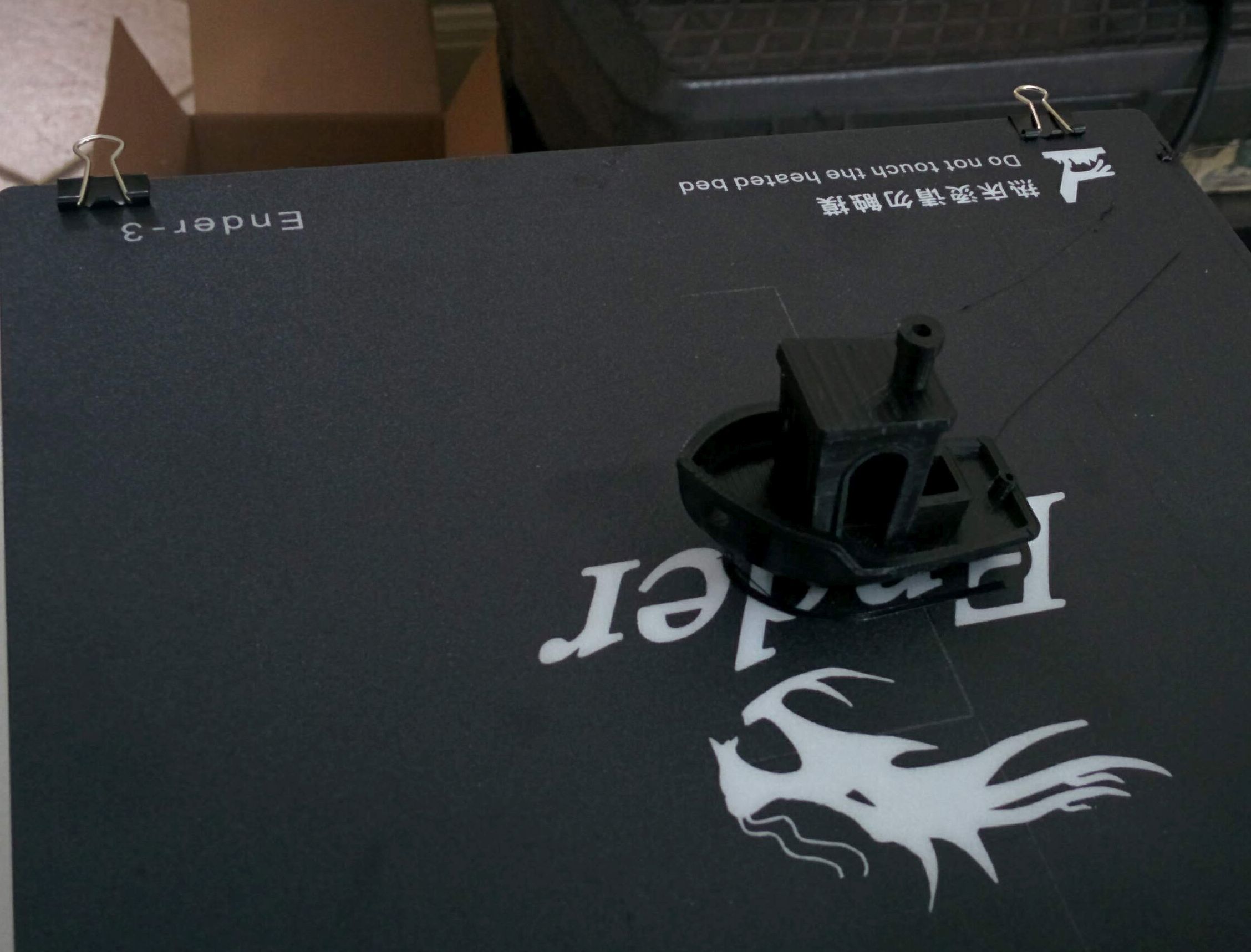
This surface is so textured, removing this "Benchy" boat was difficult
My biggest annoyance here was the binder clips. They reduce the available print area by about 10mm on all sides, so it actually is 20mm of reduction. They also cause the wires for the extruder to get hung up on them, which usually results in the clip getting pulled off mid print. This causes massive distortion as the part effectively moves up the Z-Axis when the clip is removed.
There are many different fancy and exotic surfaces you can get as a 3D Printer bed. But my solution was simple: blue painter's tape. It can be applied directly to the aluminum heated bed. The cheaper the tape the better I found. It lasts for a few prints. There is no distortion due to heating or anything like that. The only thing to realize is you need to avoid overlapping the tape or you will create small "humps" in your finished part.
Leveling the bed
After getting it assembled, the first step is to manually level the bed. Doing this accounts for the fact that the X-Y movement plane of the extruder isn't perfectly parallel to the bed. Almost all 3D printers suffer from this problem as you can't manufacture two perfectly parallel surfaces. In order to address this the Ender 3 ships with a bed that is spring mounted and the tension on each spring can be adjusted. This should theoretically work fine. The first issue is that the extruder can't travel far enough down the Z-Axis to actually get to the bed. In order to fix this you have to modify the Z-endstop, the part that tells the microcontroller that the bottom of the Z-Axis has been reached. The endstop has a small tab on the bottom that must be clipped off. Then the endstop can be slid farther down the Z-Axis. This means the stepper motor can move the extruder down closer to the bed.
From here the basic leveling process is as follows:
- Home the Z-Axis, which has the firmware move the extruder to what it believes is the "bottom" of the Z-axis.
- Move the extruder head to a corner manually with the X-Y jog functions.
- Adjust the bed on that corner until a sheet of regular paper just barely can be slid underneath the extruder head
- Repeat for the remaining corners
This is the way you would level a square bed on any CNC machine that doesn't try and get to very tight tolerances. It should work fine for the Ender 3 but it doesn't. There are at least 3 problems.
- The springs barely apply any tension to the bed
- Moving one corner up tends to move at least 2 other corners a little bit
- The bed heater has a strain relief attached to one of the bed leveling bolts
The first problem is just the result of Creality choosing the cheapest springs possible. Since they can't hold any real tension onto the bed, even the slightest bump can completely unlevel the bed. The second problem is a symptom of these weak springs as well. The popular solution to this to buy some springs from uxcell on Amazon which provide more tension than the original springs.
The third problem is just bad design on Creality's part. The strain relief for the bed heater wires attaches to the bed leveling bolt and fits underneath the spring. What this means is to get that corner of the bed level with the rest you have to compress the one spring just a little bed extra. This makes the manual leveling process just a bit more difficult and finicky than it really should be. The proper implementation of this would be to just add one more bolt and one more hole for that bolt so it doesn't have to interfere with leveling. My solution to this was to remove the strain relief. Eventually the wires to the bed heater will fatigue out and snap off, but I'll deal with that when it happens.
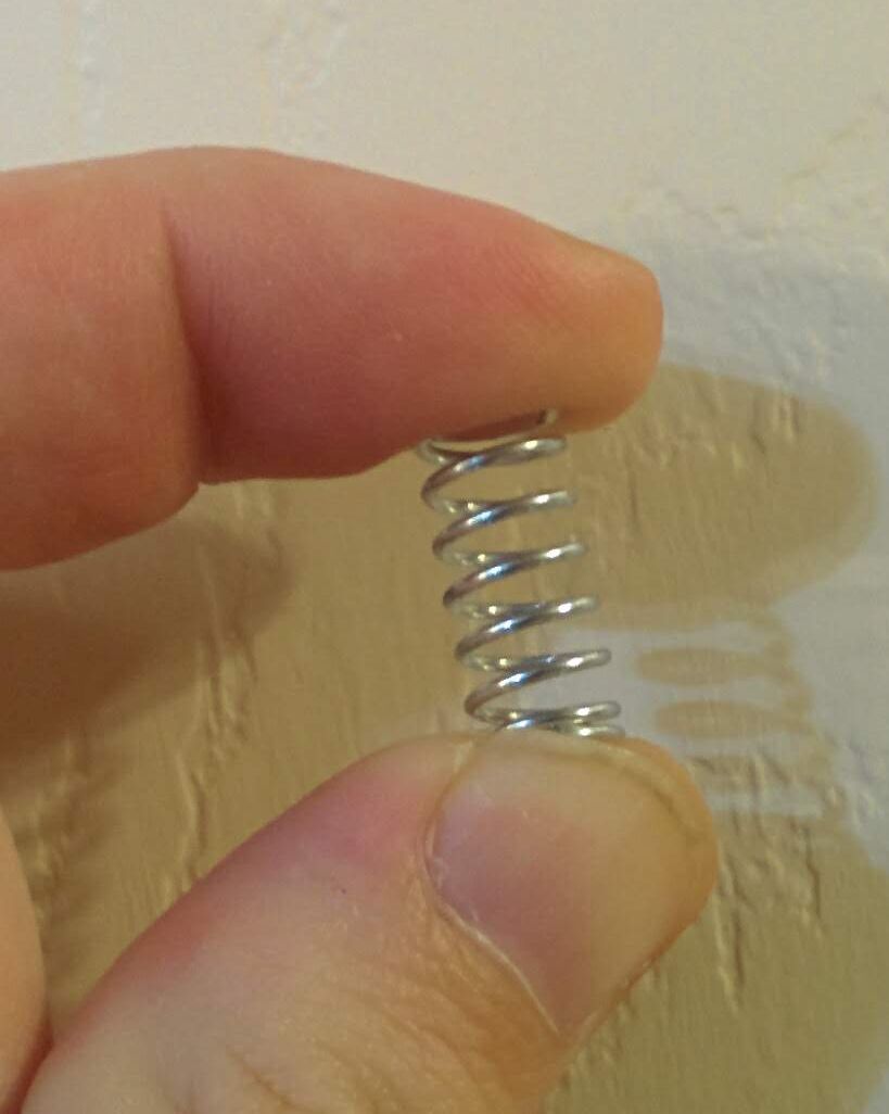
These springs hold up the bed. They aren't tall enough and don't provide enough tension.
Feeding the filament
To get the machine ready to print, you need to feed filament from a spool into the extruder of the printer. The extruder stepper has a mechanism that holds the filament snugly in place so that it can feed filament forwards and backwards. In order to feed the filament through, you need to bypass this by temporarily compressing a spring with your hand. At this point you can pass the filament through past the stepper motor. This is what you would be led to believe. But there is no mechanism to help guide the filament all the way through. All filament is curved since it comes off of a spool. So what you have to do is just stab the filament around randomly until you get it through. Once it is through it travels down a tube to the hot end of the extruder. After preheating the hot end you can manually advance the filament until it starts to come out of the nozzle. At this point you are ready to print.
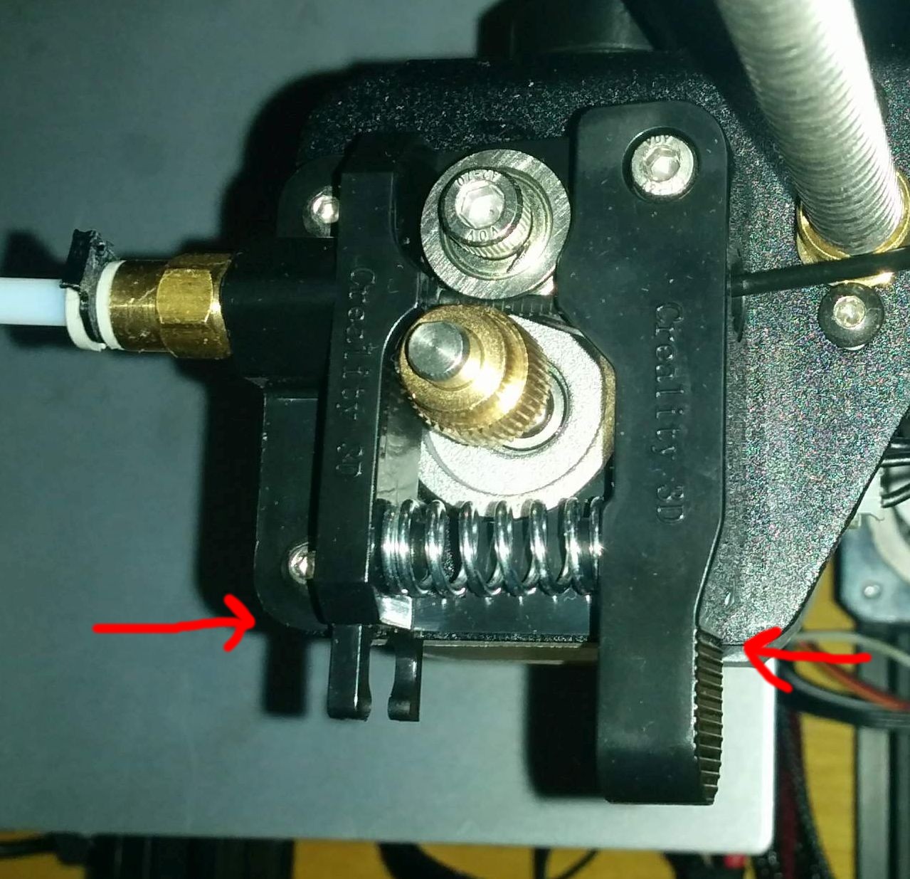
By placing your index finger and thumb on the indicated areas, you can release the filament tension mechanism temporarily
Time to print!
So at this point I was completely thrilled that I was about to make my first 3D Print. I loaded up a very basic print and told the machine to go. It dutifully started moving the extruder around. Eventually I realized nothing was actually happening. So I looked everything over. The only observation I made was that the stepper motor for extruding the filament was not actually rotating. Instead it was just rocking back and forth. Up until this point I had no idea how stepper motors actually worked. They are in fact just two phase AC motors. A stepper motor controller really just turns on one coil in the motor, then turns on the next coil, and turns off the prior one. This advances the motor a single step. So when you see a stepper motor that just rocks back and forth without actually rotating the shaft it means that only a single coil is getting power. I thought the motor might be bad, but I swapped the cable for the X-Axis onto the extruder stepper motor. It was able to run the stepper motor just fine.
At this point I decided the controller board that shipped with the printer must be bad. I contacted Creality to see if I could get a replacment, who told me I should contact the vendor I purchased the product from. I emailed BangGood but received no response. So effectively the Creality products have no warranty of any kind.
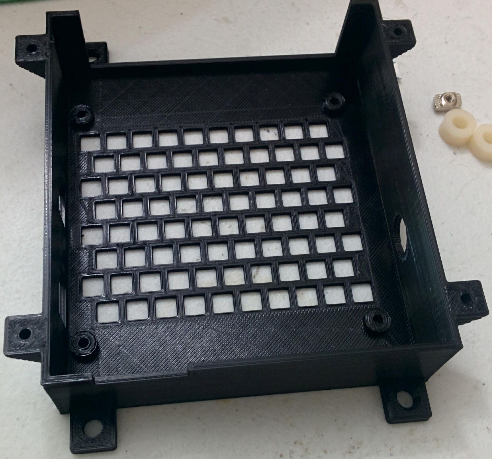
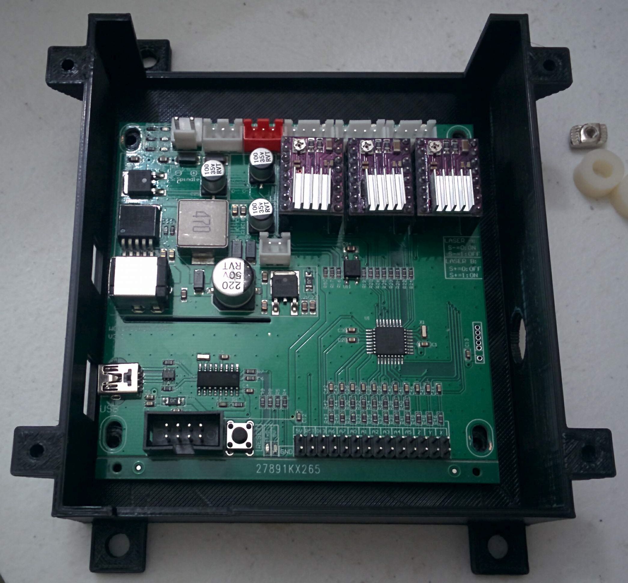
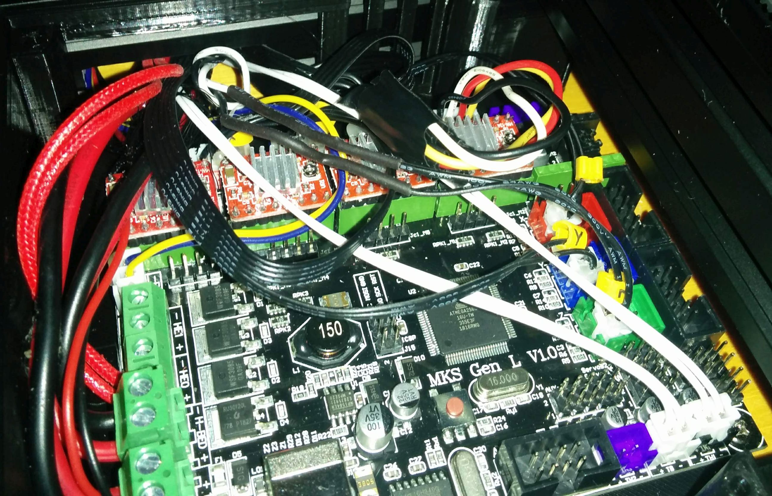
At this point I purchased an MKS Gen L and some stepper motor drivers. I needed to configure, compile, and flash the latest version of Marlin onto this board after it arrived. After getting all that setup I was left with this:
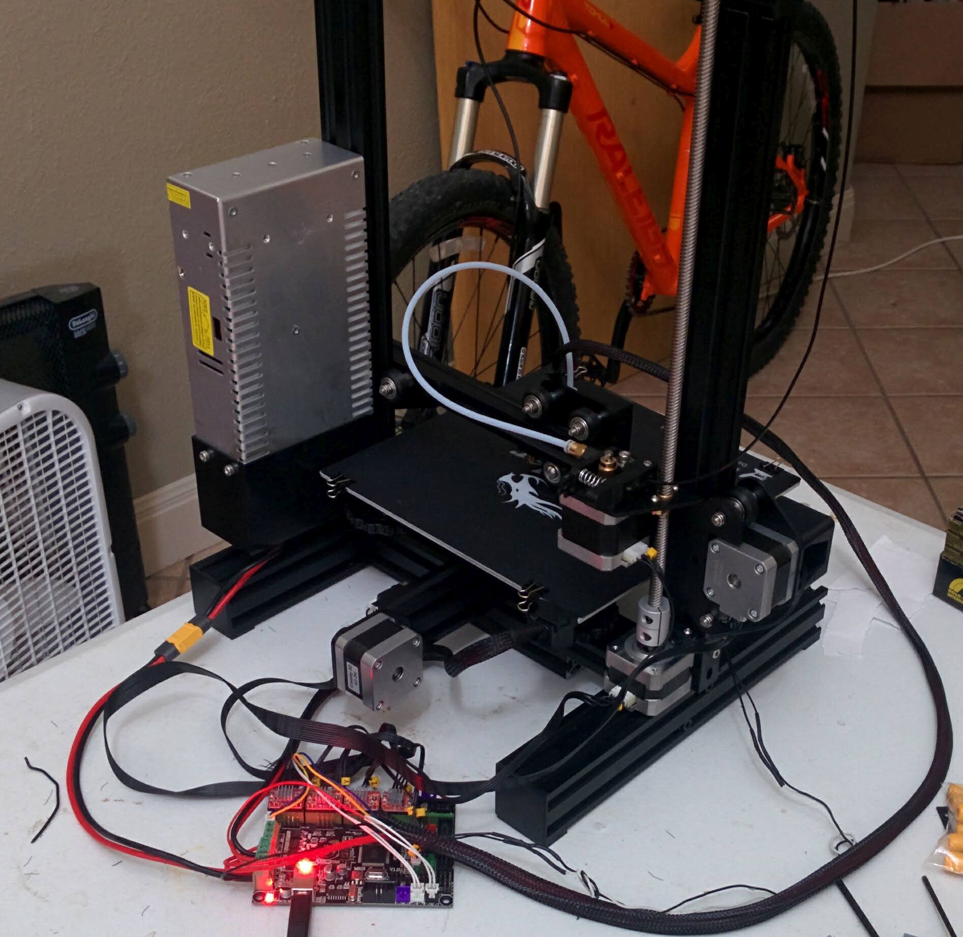
Success! I was able to print stuff. I immediately printed a new case for the MKS Gen L I found on Thingiverse. You'll notice in the above picture that the board is just hanging there by the wires. When I installed the new board into the new case I was promptly rewarded with the same "rocking" behavior of the extruder stepper motor. What I found out in fact was that the wiring that came with the printer was at fault. If I pressed on the connector for extruder motor where it connects to the controller board just right, I could get the extruder to work.
So my quick fix to this was to find another connector with the same pin style, remove those pins from that one and solder those wires onto the existing wiring harness. Then I could insert those pins in the original connector. This fixed the problem.
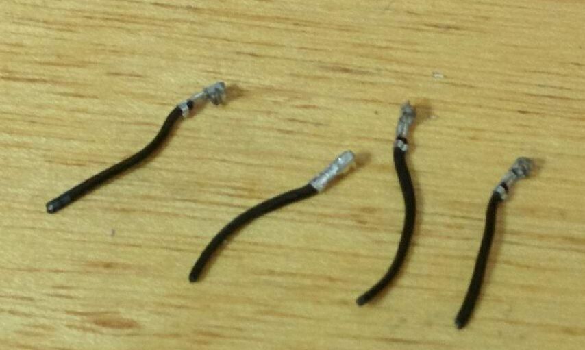
One of these pins was not making a reliable connection
In the top right is my spliced on solution
I think this is the first time I can say I have ever had a faulty pin in a piece of equipment. However, all the wiring for the stepper motors at this point is of suspect quality. The guage of the wire is very small and is more like an ribbon cable. I ordered some new wires to try and address this, but they haven't arrived yet. I would recommend anyone purchasing an Ender 3 not use the provided wiring for the stepper motors.
So is the Ender 3 worth it?
So at this point I can't really recommend the Ender 3 to anyone but very technical minded people. It has all the basics you'll need to get started. But it requires quite a large investment of time and patience to actually get it working acceptably. If you do you'll have a relatively large printer at a pretty cheap price compared to what else is on the market. If you don't think you can do all this, I recommend spending more money on a printer that has better support and is more of a turnkey solution.
My first part
The first thing I was able to design and print sucessfully was this. It's a housing for the control module of a CNC mill. I guess there is a certain amount of irony in using a 3D printer to create parts for a milling machine.