Atmega Based Thermostat Part 1
At some point in 2019 I decided I wanted to build myself a thermostat based on a microcontroller. This is the thermostat that was in the house when I purchased it, complete with mercury switch.
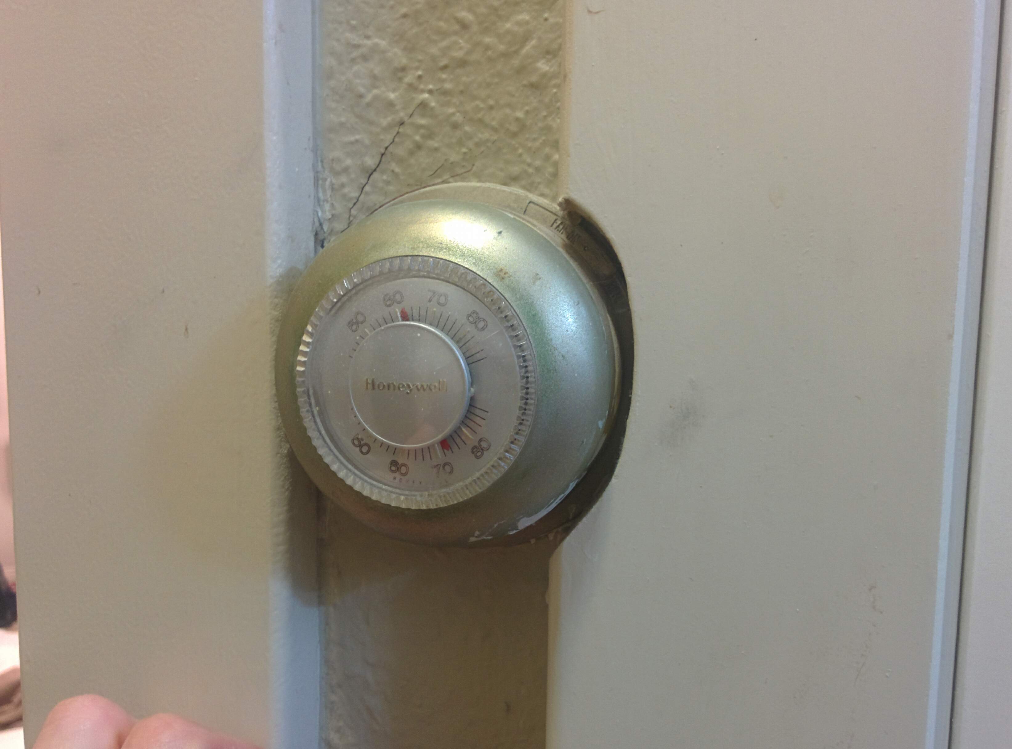
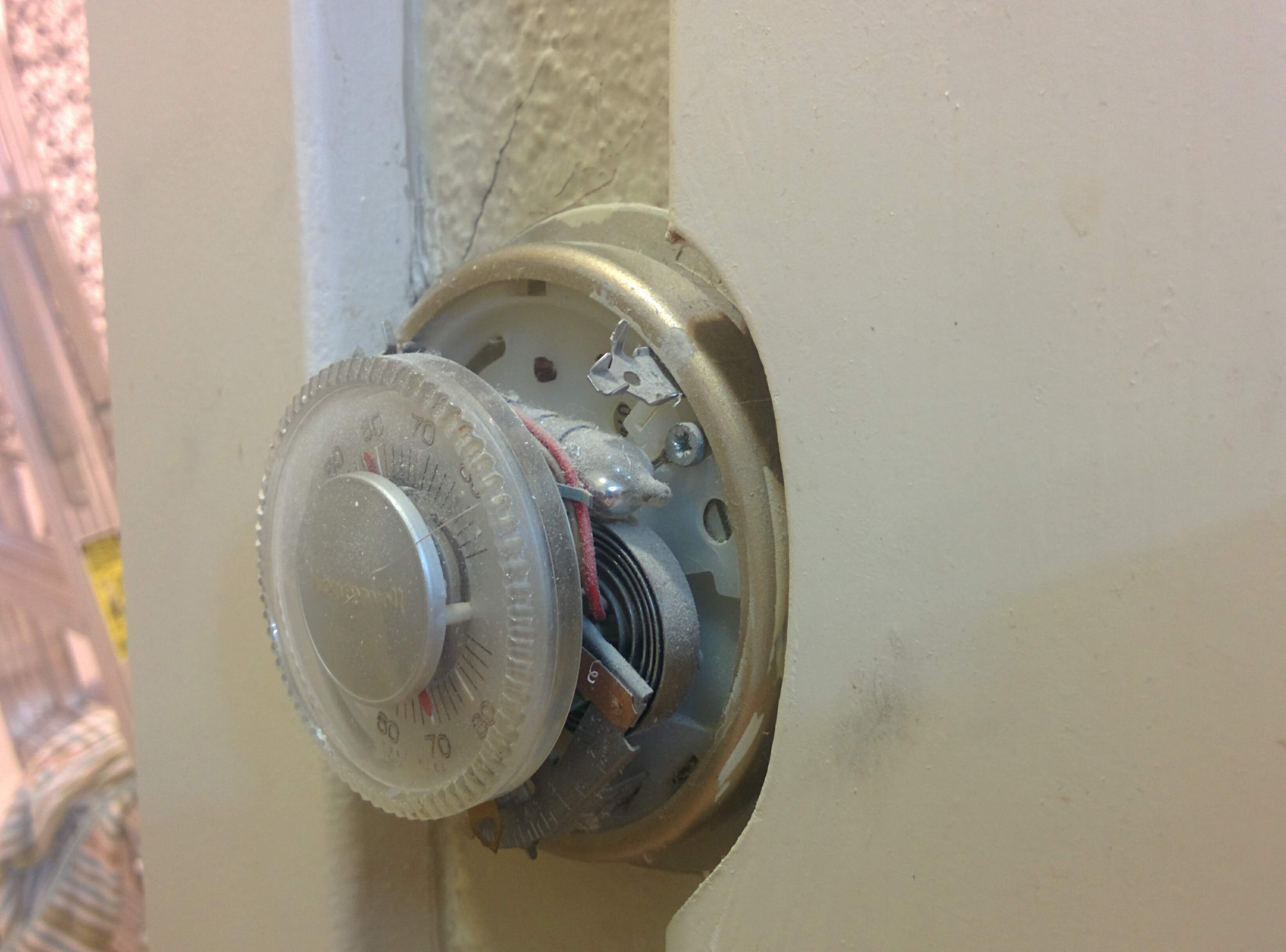
The little blob of silvery stuff in the glass tube is mercury in a sealed container. This is commonly called a mercury switch, when the container is rotated the mercury blob slides up against the contacts and completes the electrical connection. There are a bunch of other things in this thermostat like bimetal coils. All this allows a mechanical system to regulate the temperature of the house just by turning things on and off.
This is a pretty simple set of problems to approach. There are really only three things that the system can do
- If it is too cold, turn on the furnace
- If it is too warm, turn on the air conditioner
- If the user asks for it, turn on the fan
Turning on the furnace or the air conditioner implies turning on the fan as well. Most household thermostats do have an option to turn on the central fan if desired, this causes some circulation in the air.
It was with these 3 things in mind that I started down the path of solving this problem. I've decided to present this problem the order that I approached it. I have learned a great deal of things during this process. This is presented in multiple parts because of the volume of information and me not wanting to write one mega-essay.
How a thermostat works
Turning the HVAC system on and off
The first thing I needed to be able to do was turn on and off the HVAC system. In my home a 4-wire thermostat is used. This means there are 4 wires coming from the unit to the thermostat. The color of each one and function is as follows

To turn on the AC for example, a connection is made between the red lead and the yellow lead. This turns on the AC. In most residential systems, heat and AC are simply "on" when they are needed. There is no adjustment as to how much cooling or heat you get. This process of turning on and off the HVAC system to control the temperature is called "cycling". When the yellow and red wires are connected, the green and red wires are also usually connected. This tells the system to turn on the fan as well. Most systems do this anyways, but it should be done for good measure. This ability to turn the systems on and off in response to a change in the ambient temperature is the most basic of ways to consider how the thermostat works. But there are many more nuances and details I realized I needed to implement.
Hysteresis
Deciding when to turn on the AC is a pretty simple problem. Let's say the thermostat set temperature is 75 F. Once the household temperature exceeds that value the AC is turned on. But deciding when to turn it off again is a different matter. If you turned it off when the household temperature was 74.9 F the AC would only run for a brief moment. The difference between the set temperature and the off temperature is usually referred to as hysteresis of the system. The hypothetical thermostat that turns off the AC once the house reaches 74.9F has almost no hysteresis. If a thermostat has more hysteresis, it cools the house to a lower temperature before turning the AC off. I tried to do some research on this, but apparently there is no universal value for household thermostat hysteresis. I did conclude that most residential just have a fixed hysteresis of 1 degree Fahrenheit. Some possibly have an option for 2 F.
The choice of 1 F is probably because its obvious to the end user. If someone keeps a watchful eye on their thermostat and they see the reported temperature drop from 75 F to 74 F they probably expect the AC to turn off. But if it keeps cooling for a long time, they might complain to the manufacturer of the thermostat that it is defective. It doesn't mean 1 F is a good choice, just that it is a simple one.
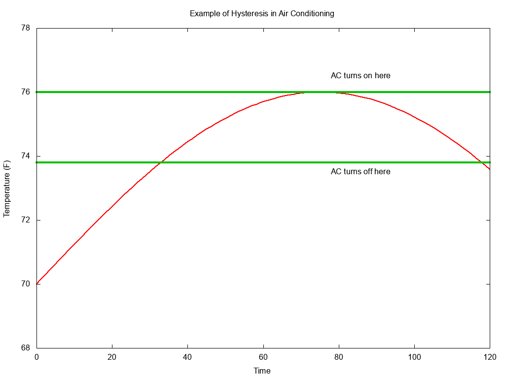
The following graph is an example of how a thermostat might be configured to turn on and off in and HVAC system. The red line is the temperature, and the green lines represent the temperature at which the system turns on and off. The system in this example has a little bit more than 2 F of hysteresis, shown by the difference in the green lines on the Y axis.
I chose to make the hysteresis a configurable value, but not through the user interface.
System cycle times
The other important thing I learned in the process of all this is that you don't want to turn your AC system on and off quickly. This is called "short cycling". Basically the house warms up, but when the AC turns on it can quickly cool the house down. This process then repeats many times per hour. This stopping and starting of the compressor isn't the best idea. In some cases it may even cause damage. I could not find any specific limits as to how stops and starts per hour my AC unit is rated. What I did find is that the compressor requires a minimum off time of 3 minutes. Oddly enough this note was in the wiring diagram.
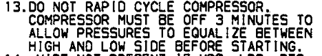
The manufacturers warning about cycle time
The reason why this is important is that air conditioning systems in most climates are designed to handle peak load. This means that on the hottest day of the year, the AC should be able to run 100% of the time and keep the house at a nominal temperature like 75.0 F. Where I live in Texas we see extreme temperatures of 103.0 F or higher sometimes for multiple weeks. I know my air conditioning system is capable of controlling the household temperature even on those days. What this means is that on a typical hot day where the outdoor temperature is 95.0 F, I have lots of extra cooling capacity available.
So there are two intervals here: the minimum time between cycles (the off time) and the minimum cycle time. The minimum time between cycles is a hard limit supplied by the manufacturer that should not be violated under any circumstance. The minimum cycle time is really a matter of preference. In theory if your air conditioning can cool your house down in 2 minutes, that is fine. There is a great deal of speculation on the internet as to the optimal cycle time for power savings, but I don't really care about that. My current home is tiny and well insulated, so my power bill is very low.
One interesting note is that the mechanical thermostat on the wall has no concept of minimum off time at all. So I suppose the system has been running for a very long time without this protection. The cycle time of the mechanical thermostat is loosely controlled by how long it takes for the bimetal coils in it to cool down.
I wanted to prevent short cycling to avoid premature failure of my compressor. The furnace is actually natural gas, so I don't think the same concerns apply there. I had a bunch of neat ideas about how to prevent short cycling. Initially I had the idea of the averaging the household temperature over a 6 minute period. This did in fact create long cycle times. However, I decided this was not a very good solution. The most basic example is what happens when someone leaves the door open on a hot day. It could take up six minutes before the thermostat decided to start cooling the house. This is a problem on the hottest days of the year because it can be difficult for the system to keep up anyways. My actual implementation was just to set a minimum cycle time of around 10 minutes. This seemed appropriate for my house, but probably is not perfect for all applications.
Locking out system changes
The other thing a thermostat needs to be capable of doing is responding to user changes very slowly. The might seem strange, but consider if the air conditioning is already on and the user attempts to adjust the set temperature downwards. But they make a mistake and hit the set temperature increase button. Since it takes many minutes for the system to change the ambient temperature there is no reason to start making changes immediately. What you can do is show the user the change on the user interface. In my hypothetical scenario above, the user would see their mistake and then adjust the set temperature the correct direction. In the interim time period, the thermostat hasn't actually changed anything about what it is doing.
The way I chose to deal with this is just preventing any actual changes to the climate control for a minimum period of time after a button press. I call this the user change lockout time. Each button press raises a timer up to that value. When that timer expires the changes to the system can actually take effect. This means that as long as the user is still adjusting things, the thermostat doesn't take any actions other than to update the display.
Complete feature set
- It has to be able to selectively switch 3 electrical circuits
- It has to mount on a wall
- It needs to run on a low voltage
- It needs to be able to measure the temperature
- It should have an dot-matrix style LCD
- It should have four buttons for control
- It should lockout changes when the user is actively using the interface
- It should have some form of external connectivity
Building a prototype - the hardware
Since I realized this would be a learning experience for me, I decided to assemble this project using the part I had available already.
The microcontroller
I chose for this project an Atmega328PB board I bought off AliExpress. This board looks like an Arduino Nano, but it isn't. First off the Atmega328PB isn't actually supported by the Arduino IDE. The USB connector is also a different type. It does mostly share the pinout and board specification. One advantage of the Atmega328PB over the Atmega328P is that it has two UARTs.
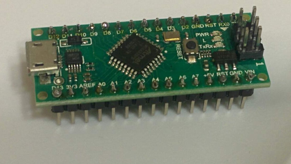
An Arduino-ish chip
Temperature sensors
The temperature sensors I chose are the DS18B20. These sensors are available on AliExpress for a little over $1 each. Each one is conveniently packaged into a metal tube, wires are attached, and it is sealed. They have 12-bit accuracy and can be sampled about once a second. They are overkill for this application, but should work fine.
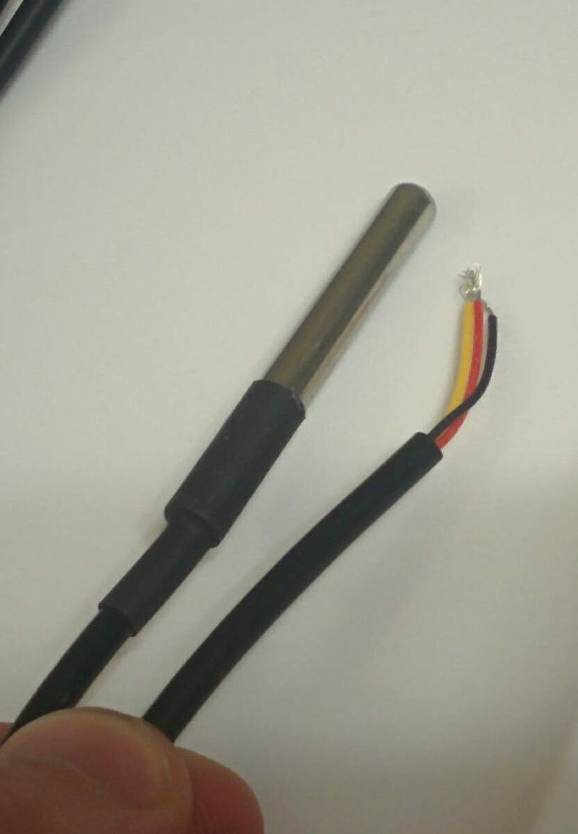
Why multiple sensors? Well it'd be neat to have a bunch scattered around the house but that isn't what I'm trying to do with this project. I threw in multiple sensors because they are cheap and I've always been curious how hot or cold my HVAC system actually gets in operation.
Relay
As mentioned earlier, turning on the AC or heat consists of nothing more than connecting two wires together. To make these electrical connections I chose to use some small relays that are designed to mount on a printed circuit board. This is simple and relatively robust. The relays do not need any particularly large current ratings as the electrical connection here isn't actually switching the AC or heat on and off. There is another relay mounted at the exterior compressor that switches mains voltage on and off. The voltage present at the thermostat is only 24 VAC, which is relatively harmless unless you stick the wires into your mouth. The relay I chose is a HF33F relay, which is overkill for this application. They were what I had on hand.

The other important feature of relays is that they have a certain amount of electrical isolation between the circuit being switched and the circuit that controls the relay. This is due to the mechanical nature of relays. The coil has current passed through it to move the contacts. The coil is one path for electrical current and the contacts are a different electrical circuit. This is an important safety measure, because it means if something goes wrong with my thermostat, it should be almost impossible for it to electrically damage the HVAC system.
The OLED display
The OLED display I got is a SSD1306 type display. It appears to have very strange markings on it which would indicate that it is SPI, but in fact it is an I2C device. Each board was marked "GM009605 v4" on the backside. That eventually led me to this website explaining how they work. It appears that since I found that page, the HTTPS certificate has expired.
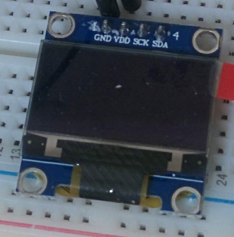
This is just a poorly labeled SSD1306
This is an incredibly common display, commonly available for $1 or less.
Connectivity
I wanted some way of remotely controlling the thermostat in the future. The microcontroller board has the USB connection that acts like a serial port, but that is impractical unless I had a PC nearby. There is the option of trying to add WiFi, but I don't really want the extra headache of figuring all that out. I chose to add an RS485 connection. RS485 is just another voltage level standard for serial data exchange. It is by default however half-duplex so it doesn't really work the same way. It's also multi-drop, meaning a large number of devices can be on one serial bus. This means that the serial bus basically works like a noisy hallway. If one person speaks (transmits) at a time, all other parties can hear (receive) it. If two parties speak (transmit) no one can hear (receive) any of it. The conversion between the TTL voltage levels of the microcontroller and those used by RS485 is done using a MAX485 chip. These are actually little surface mount devices that I don't want to bother with soldering. So I bought off AliExpress some that are mounted on a carrier board that has 8 pins and a convenient set of binding posts to make the connection to the bus. I'd like to note here that although RS485 looks like a two wire bus, you actually need 3 wires. You need to use a common ground between all devices on the bus.
As I will describe in a later installment, I used this RS485 connection to add ModBus connectivity to the thermostat.
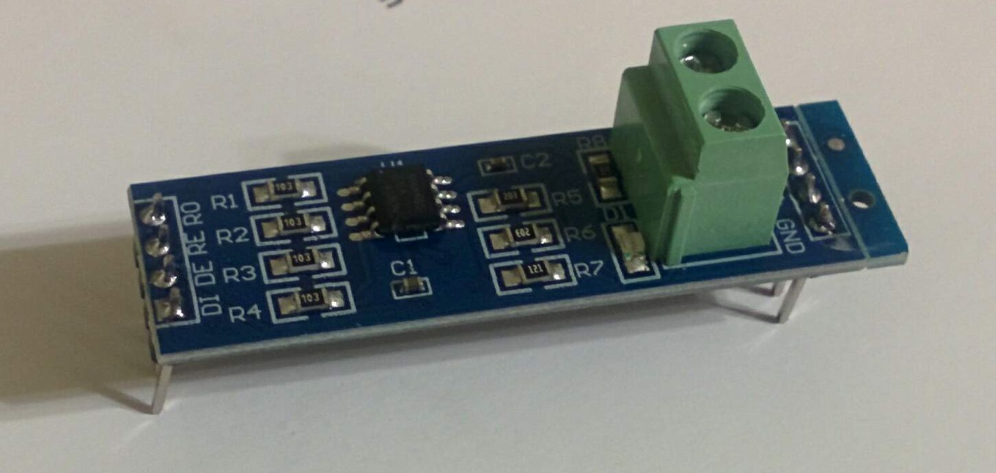
The surface mount MAX485 is mounted on a breakout board with pins and terminals
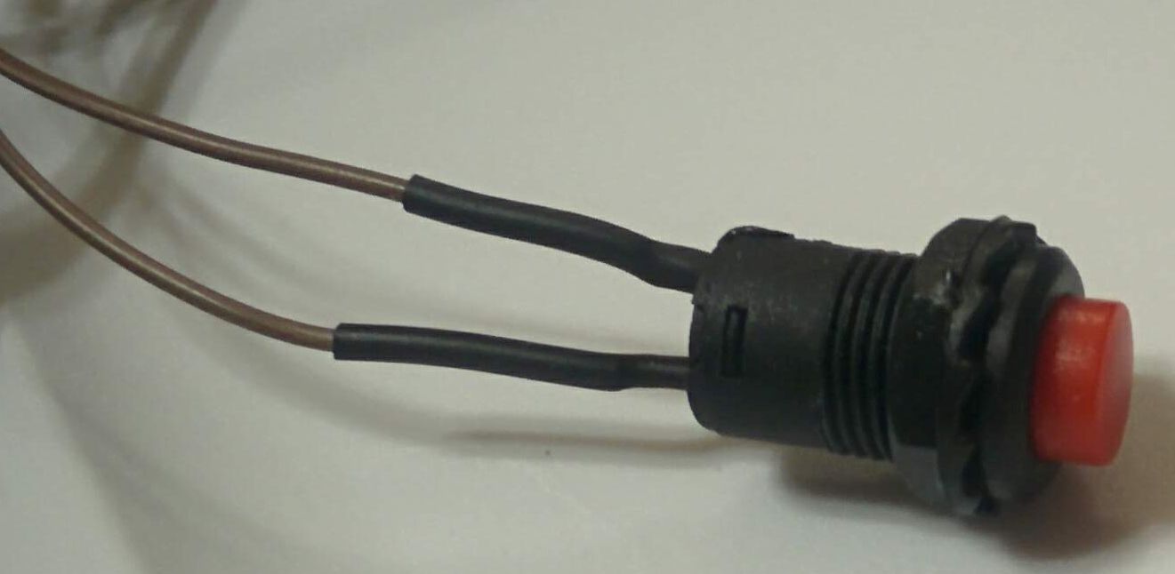
Buttons
The buttons I am using are typical push buttons that are normally-open. When you press the button, they complete the electrical circuit. They are made primarily of plastic and mount in a 1/2-inch hole.
Designing the circuit board with Fritzing
When building a project like this, you'll wind up needing to make lots of electrical connections. A common way to do this is with breakout boards and individual wires. The wires can be secured with terminals or soldered in places. This is convenient, but is actually time consuming and expensive. Projects built like this usually wind up taking up a large physical volume as well.
So I decided to make my own printed circuit board. I didn't know at the start of this project all of what I needed to put on the board, so I just decided to include the following
- A socket for the microcontroller board
- Relays
- Terminals for the relay contacts
- Transistors to control the relays
- LEDs to indicate what relays are on
- A place to mount the MAX485 unit
So this doesn't cover everything I need. What I did to account for this was to add another row of male pins along the microcontroller socket. This allows me to connect up anything I need to any pin later on, which proved to be very important. So this PCB acts something like a generic breakout board for the module as well.
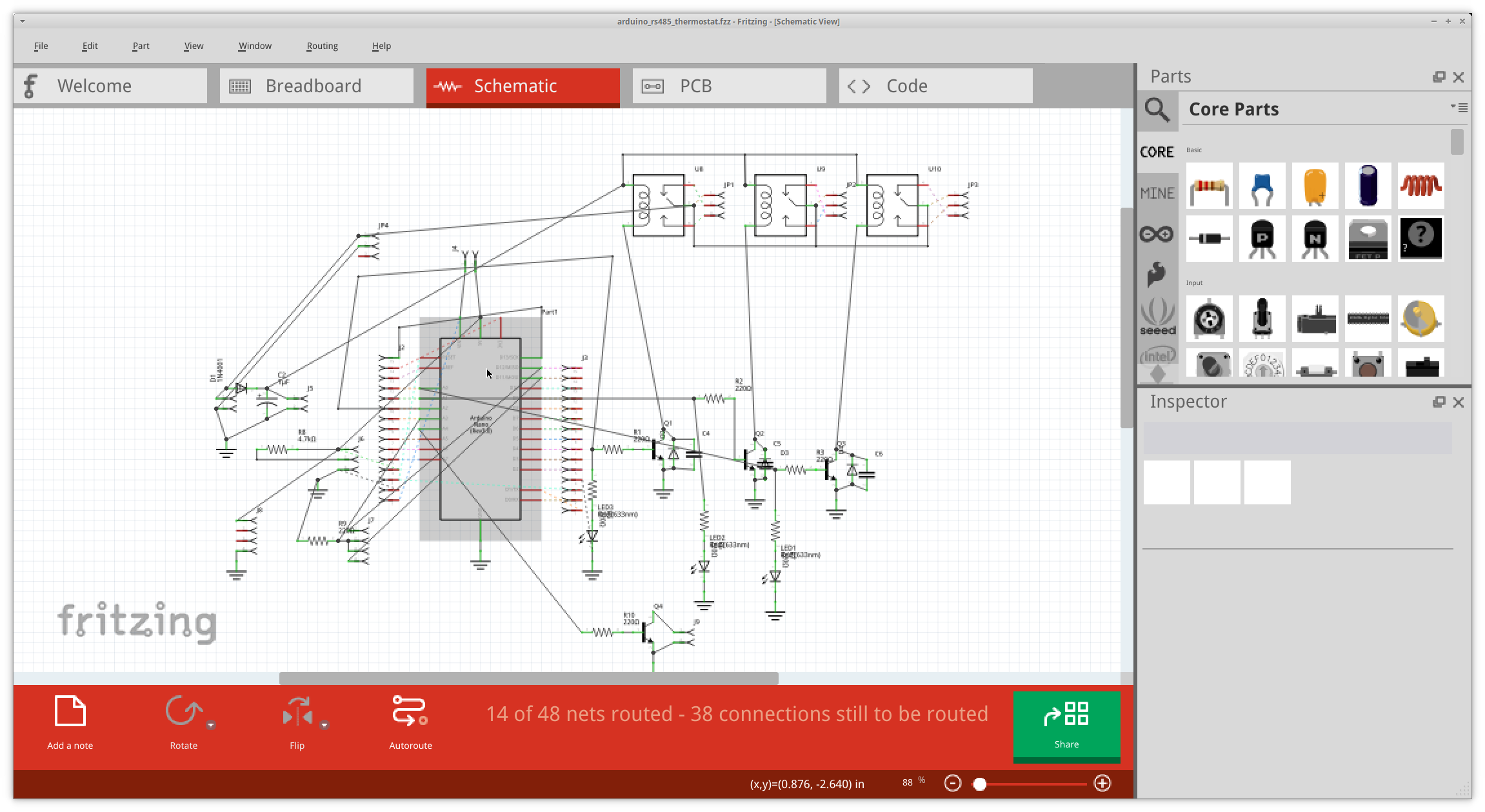
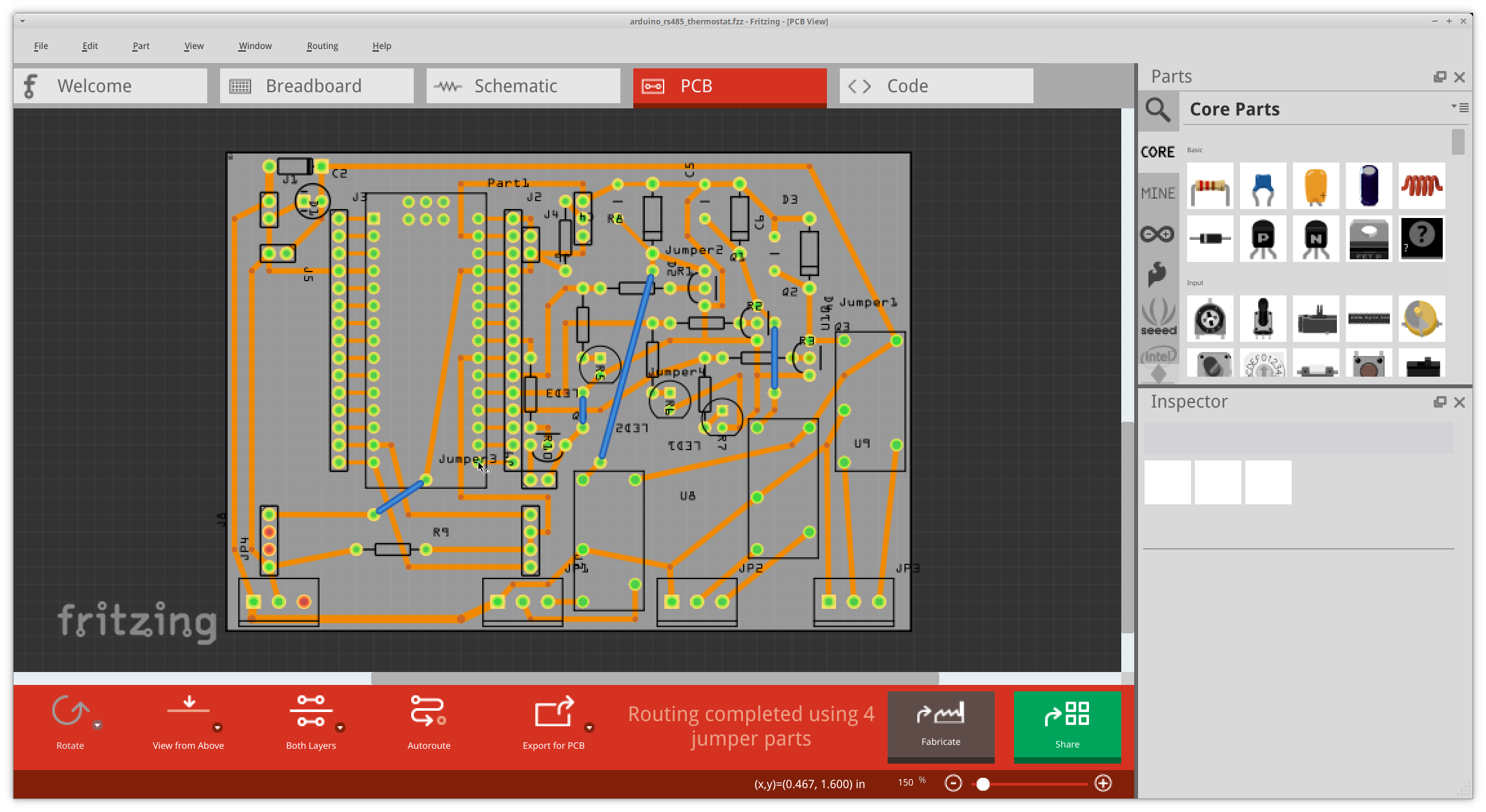
I won't go into details about how I built this other than to say I used Fritzing and the standard laserjet printer method of transferring the board design onto a copper clad board using glossy photo paper and extremely high heat. Fritzing isn't a perfect piece of software, but it will in fact get the job done for simple projects like this. Professionals will find it lacking in features, but it allows you to quickly lay out a schematic and then also do a PCB layout with the same components. The user interface is less than perfect, but the software is free and has a low learning curve.
Building a box
So at this point I need a box to house everything. I couldn't really find anything reasonably priced, so I decided to build something. I knew I'd probably wind up revising this project sooner or later, so I wanted to build something simple that would work. I built a simple box with some scrap wood. I even managed to make a mount for the PCB that it could slide into from wood. I used my table saw to cut some little slots into small chunks of wood that the PCB can rest in. Gravity is able to hold it in place.
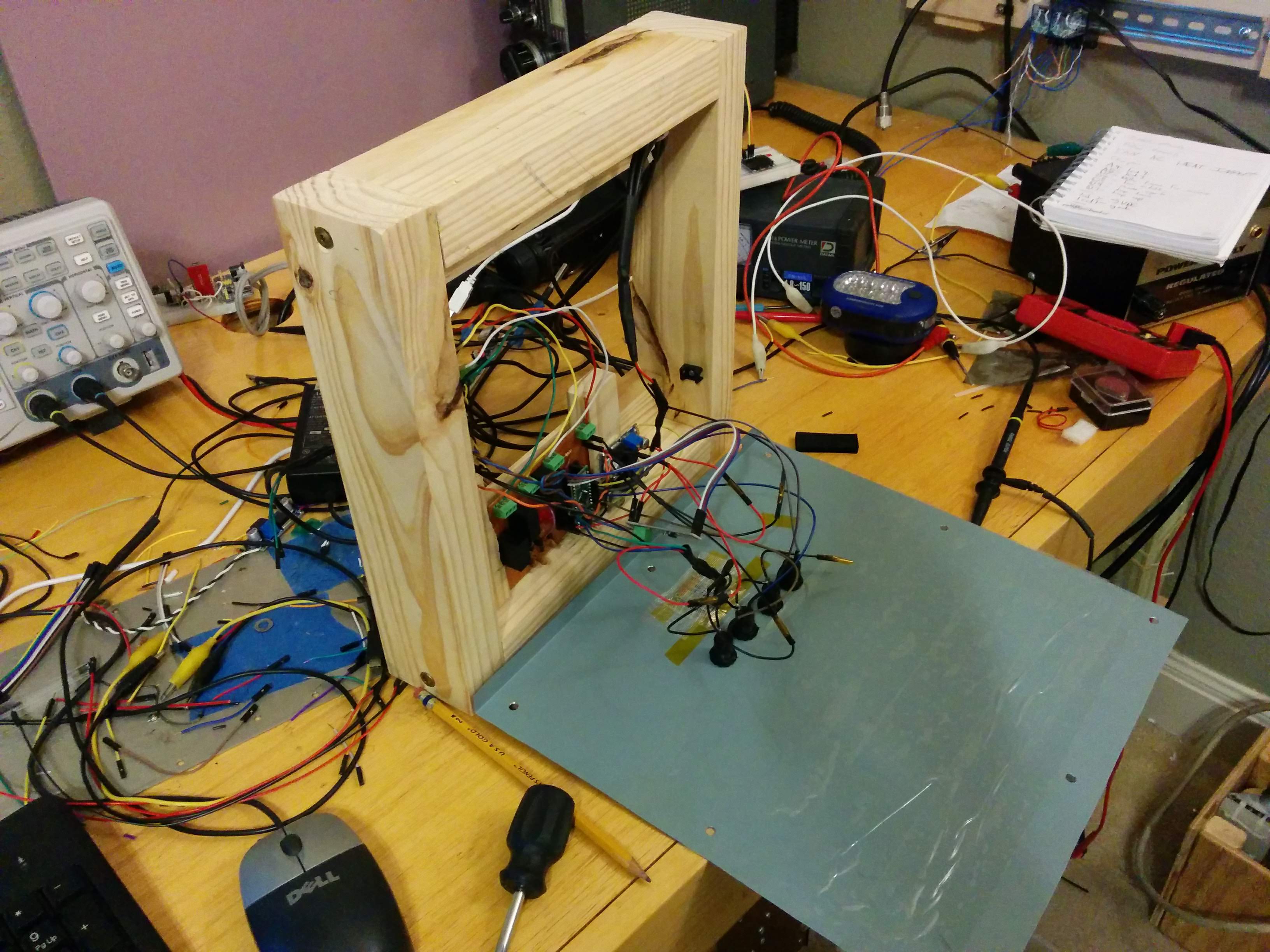
The front panel of the boxs was created by repurposing the exterior of an old microwave oven. I have a nibbler tool that allows me to cut the steel panel to shape. It is very thin, around 0.1mm so it can be cut with little force fron the handheld nibbler. Holes were drilled for the switches. To create the rectangular hole for the display I just roughed out a hole with the nibbler, then filed it to approximately the rectangular shape. The LCD was simply taped into place. The wiring on this was obviously an afterthought. This isn't a very pretty thing to put my project in, but it works for now.
End of part 1
That's it for the end of part 1! In the next installment I'll cover the software side of this project.