Configuring OpenWRT for VLAN isolation of WiFi networks
I have a need to have multiple WiFi networks in my house. I want them to be isolated to some degree but to share the same physical Ethernet network. The normal way to do this is with VLANs. The use of VLANs tags each frame with a number that identifies that network. For my WiFi I've used OpenWRT running on a Linksys WRT3200ACM for a while. So what I wanted to do was to setup OpenWRT to have separate WiFi SSIDs for separate clients. Whenever WiFi traffic arrives at the OpenWRT box I want it to tag the ethernet frames from that network as a specific VLAN identifier.
I'm using a Linksys WRT3200ACM which is the typical "home router" in a single box. Almost all home router appliances internally are a 6 port managed switch with a single ethernet port connected to a system on a chip. There is one ethernet port plugged into the switch & the switch is divided up into 4 ports for the "LAN" and 1 port for the "WAN". The newest version of OpenWRT support what is called "Distributed Switch Architecture". This means we can leverage this managed switch to do what I want. I flashed OpenWRT 24.10.4 to my WRT3200ACM for this. Almost any home router box than OpenWRT supports is going to work with this, but you should probably check the product page on the OpenWRT wiki to make sure. I'll also mention at this point that I while I use OpenWRT as an access point I don't normally use it as a DHCP server or internet gateway.
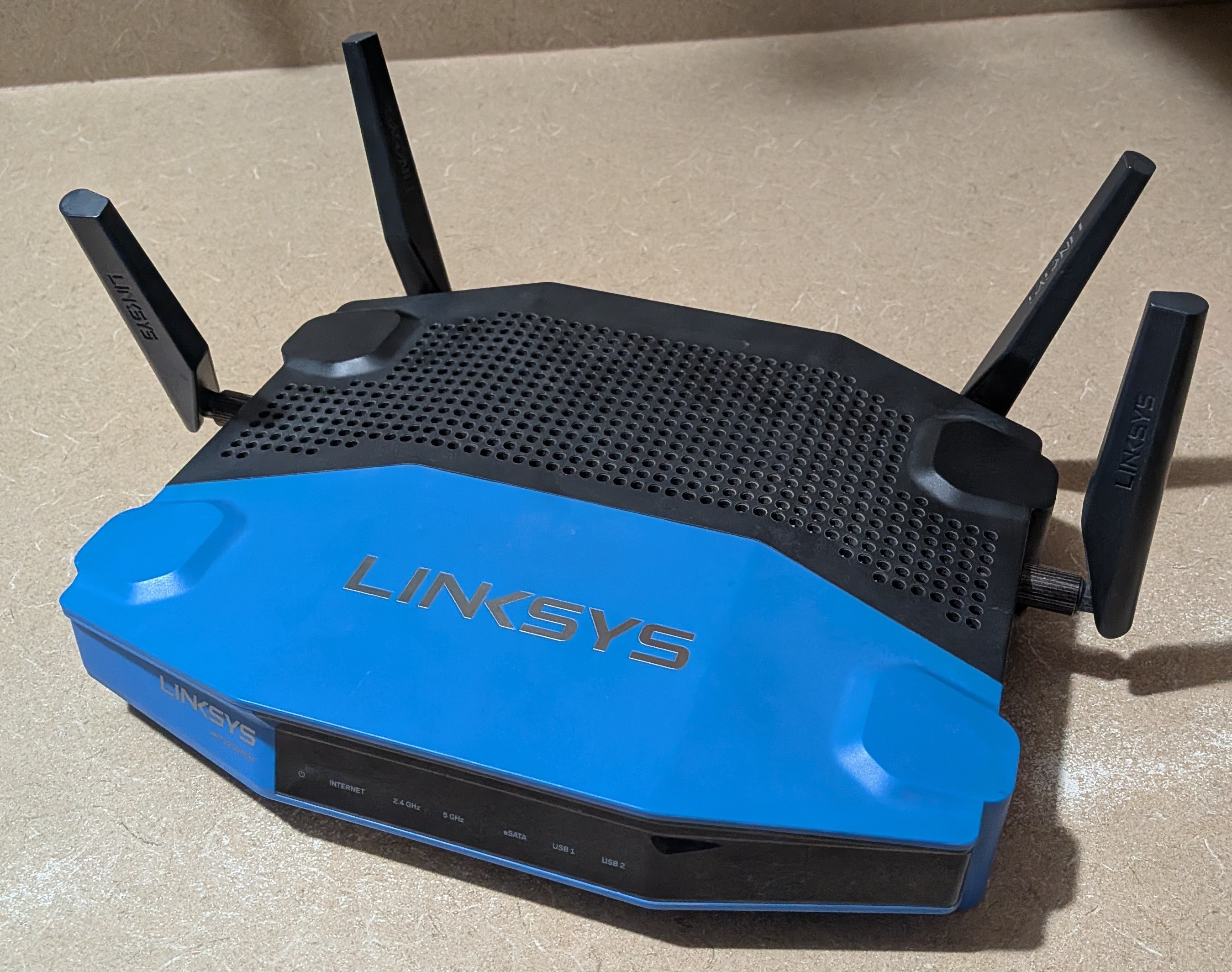
The rather dated yet reliable Linksys WRT3200ACM
The network configuration I want to setup on OpenWRT is this
| Network name | VLAN | Description |
|---|---|---|
| LAN | None | The regular home network |
| LAN-IOT | 100 | A network for IoT devices |
| LAN-Guest | 101 | A network for guest devices |
This is simple to describe, but I ended up getting it wrong several times. Normally this would not be an issue because I could just adjust the configuration until I got it working. However the Linksys WRT3200ACM has no easily accessible console because it is just a home router box. The primary mistake I made was using the console over SSH to try and reconfigure things. It is possible to do the configuration this way but using the web based graphical console LuCI is a better idea. If you make a configuration change in the web console that results in a loss of connectivity, it automatically rolls back that change. This means I was able to get it wrong as many times as I needed to without having to use the reset button on the router.
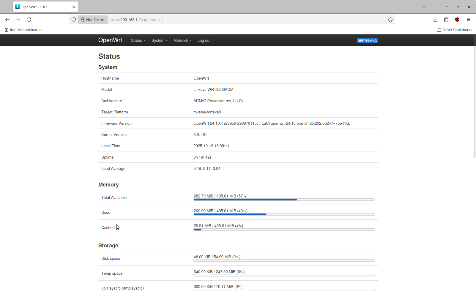
When you install OpenWRT this is the page you see
Step 1: Reconfigure the internal switch for VLANs
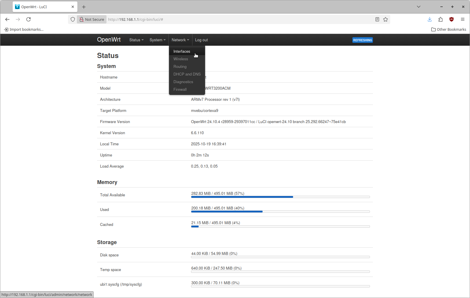
From the status page you can navigate using the top bar on the page. Click Network and then click Interfaces as shown here
This page has multiple tabs on it, click the Devices tab to get to this view
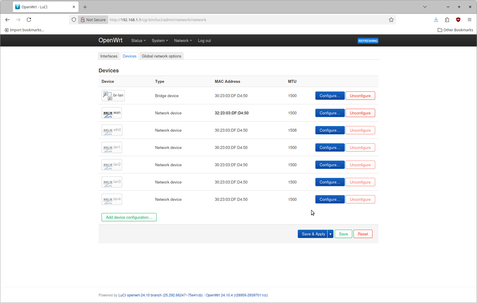
The top entry is the device "br-lan". Click the button "Configure" on the right hand side. The configuration page looks like this by default
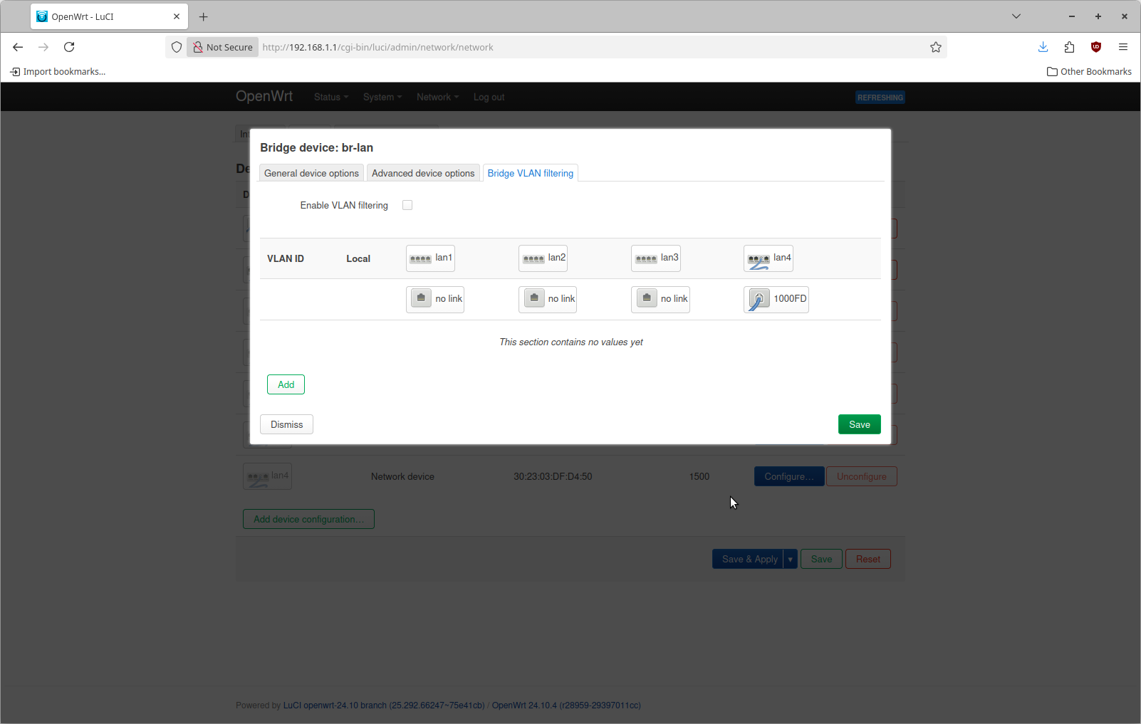
The reason why lan4 shows 1000FD is that I have plugged into that port on the router from my desktop. At the top check Enable VLAN filtering. Then use the add button to define 3 different networks as shown here. Do this on what ever port you have plugged into on the device
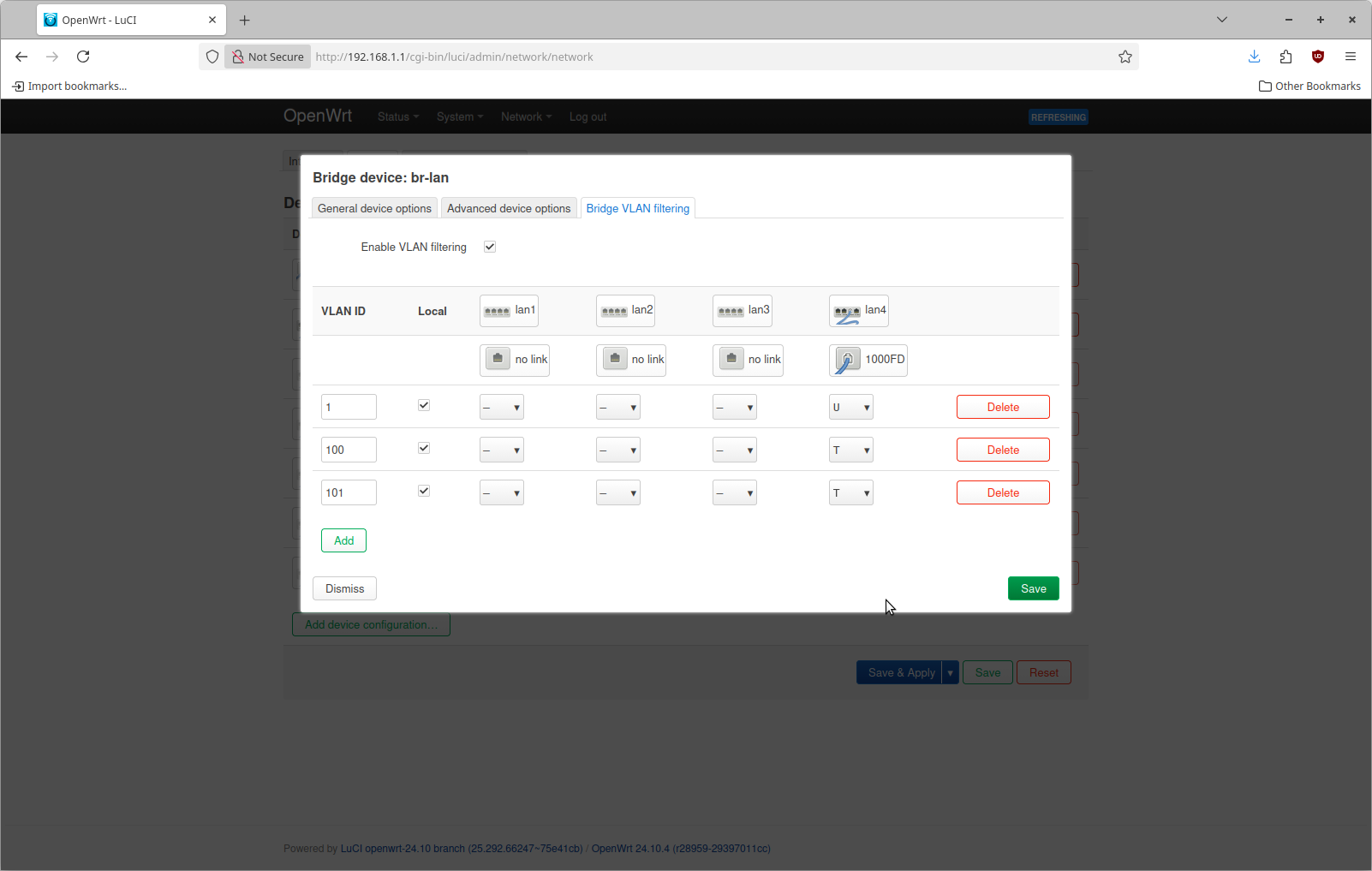
If you compare this with the network configuration I want, this may seem a little bit different. The bottom two entries I've added are for VLAN 100 & 101. These are configured with a value of "T" for port 4 which means "tagged". I also added a line for VLAN 1 that is configured with a value of "U" for "untagged".
The terminology around VLANs, port virtual IDs, etc. is quite confusing to me. For the purposes of this we can consider the meaning of each one as follows
| Configuration | Description |
|---|---|
| Untagged | Ethernet frames on this port without a VLAN tag are tagged by the switch to this VLAN |
| Tagged | Ethernet frames on this port with this VLAN tag are allowed in both directions |
The reason why VLAN 1 is configured is because internally the router needs some way to identify untagged frames. The managed switch on most routers is incredibly powerful. An untagged ethernet frame is a fancy way of saying an ethernet frame that does have VLAN on it. This is what basically every device sends by default if you just plug your laptop into a network with an ethernet cable. By telling OpenWRT to tag an untagged frame with VLAN 1 we are able to identify this network traffic.
The other two entries are simply telling OpenWRT to allow traffic tagged with VLAN 100 or VLAN 101 to both arrive and depart on this physical port.
There are probably dozens of valid ways to use the internal managed switch of this device. We're not done yet. This description is a simplification of things & serves the purposes I need. Do not save and apply at this step. We need to reconfigure the device associated with the interface in OpenWRT. To do this click on the Interfaces tab on the page you are already on.
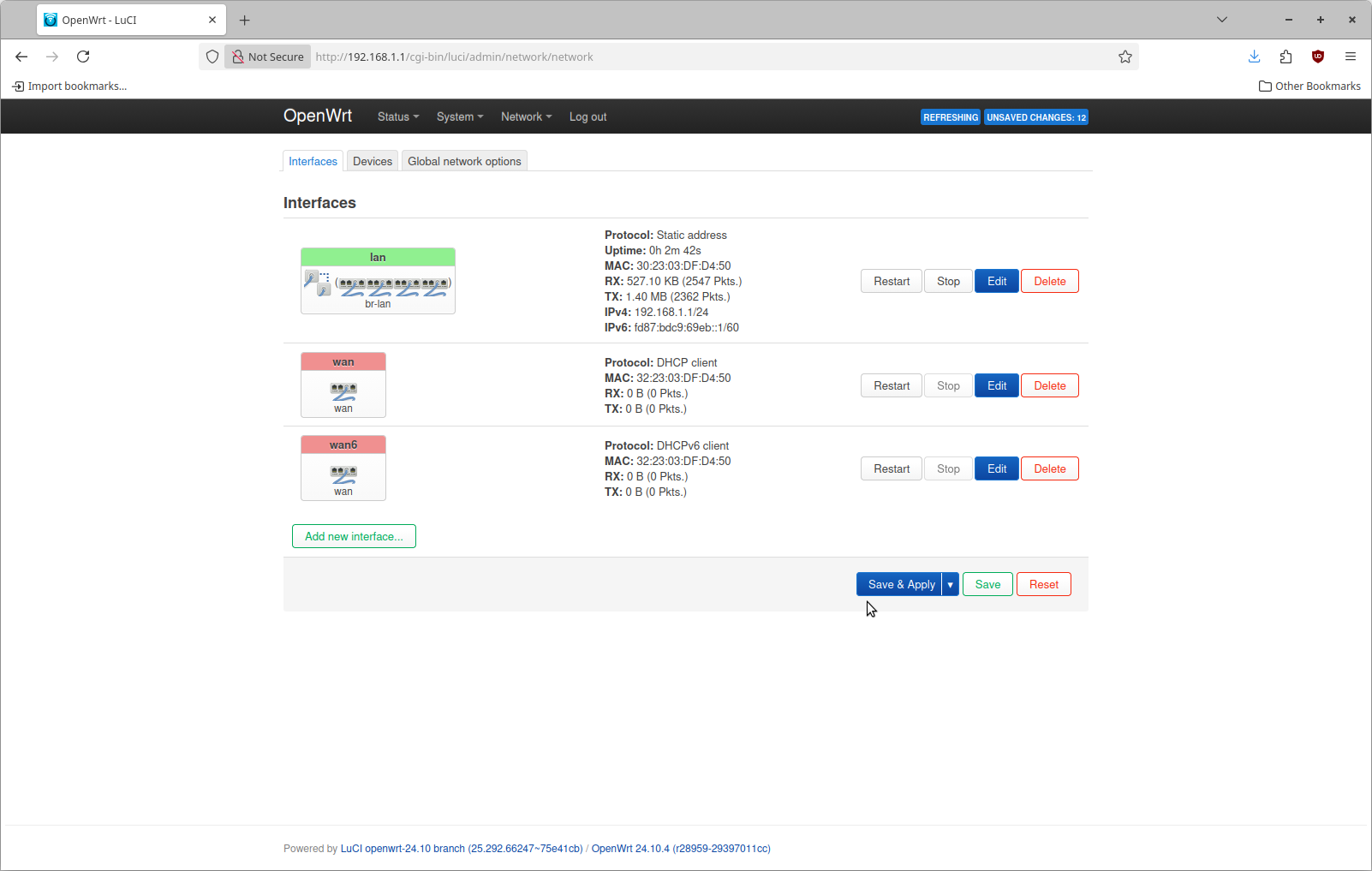
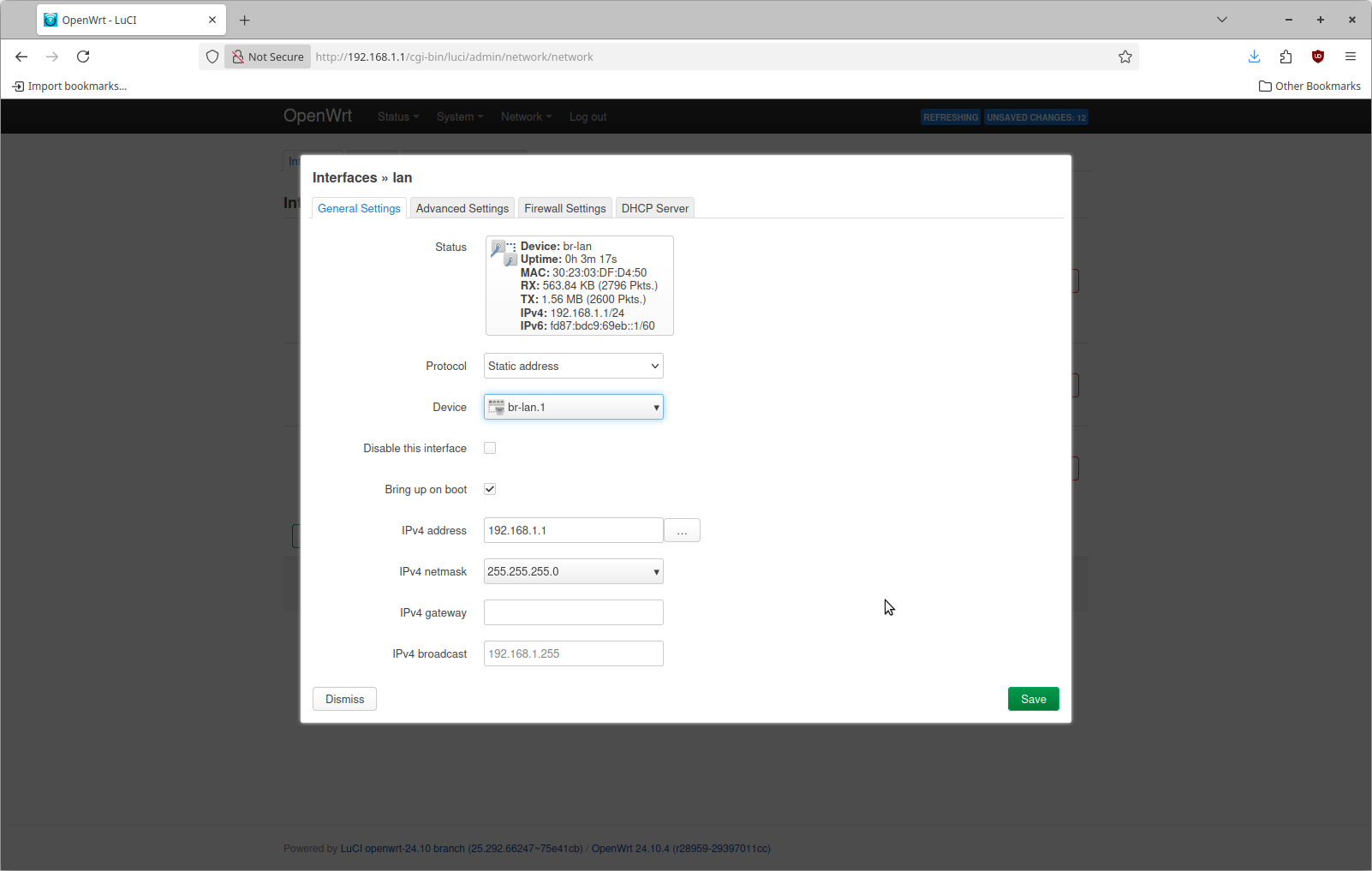
This is what it looks like by default. Click Edit on the top entry named "lan". The configure for this by default is going to specify a device of br-lan.

With the switch now configured, there is no longer going to be any ethernet frames arriving internally on br-lan. This needs to be reconfigured to br-lan.1. Change the device as shown here
At this point you are ready to save & apply this configuration. When you do that you should see a screen that looks similar to this

Now save & apply this configuration change. You will briefly lose connectivity during this time period.
Step 2: Add additional interfaces for VLANs
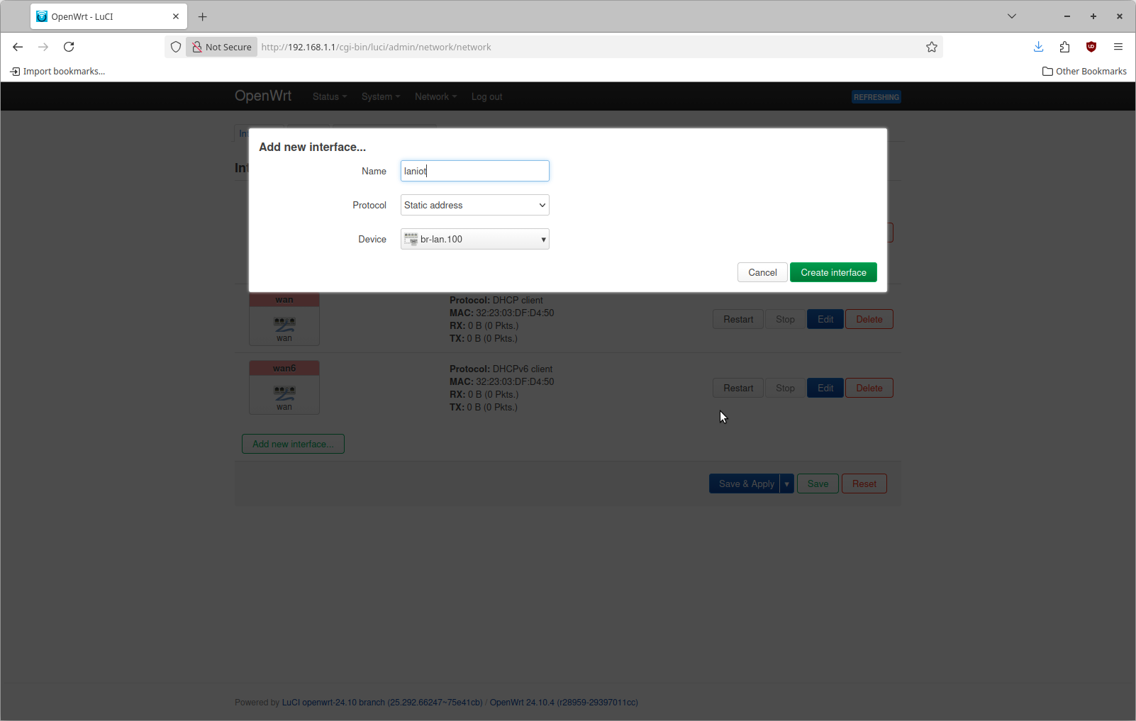
Now we can configure two additional interfaces, one for each VLAN. This is done by navigating to the Interfaces tab again and selecting Add New interface. For the name specify laniot, a protocol of Static Address and a device of br-lan.100. This device is the one corresponding to VLAN 100
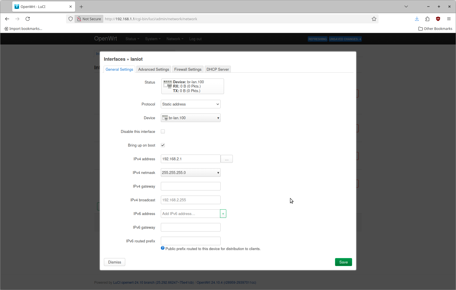
Click Create Interface to proceed. Then fill in an IPv4 address of 192.168.2.1 with an IPv4 netmask of 255.255.255.0. In my case I am specifying a unique subnet for each VLAN
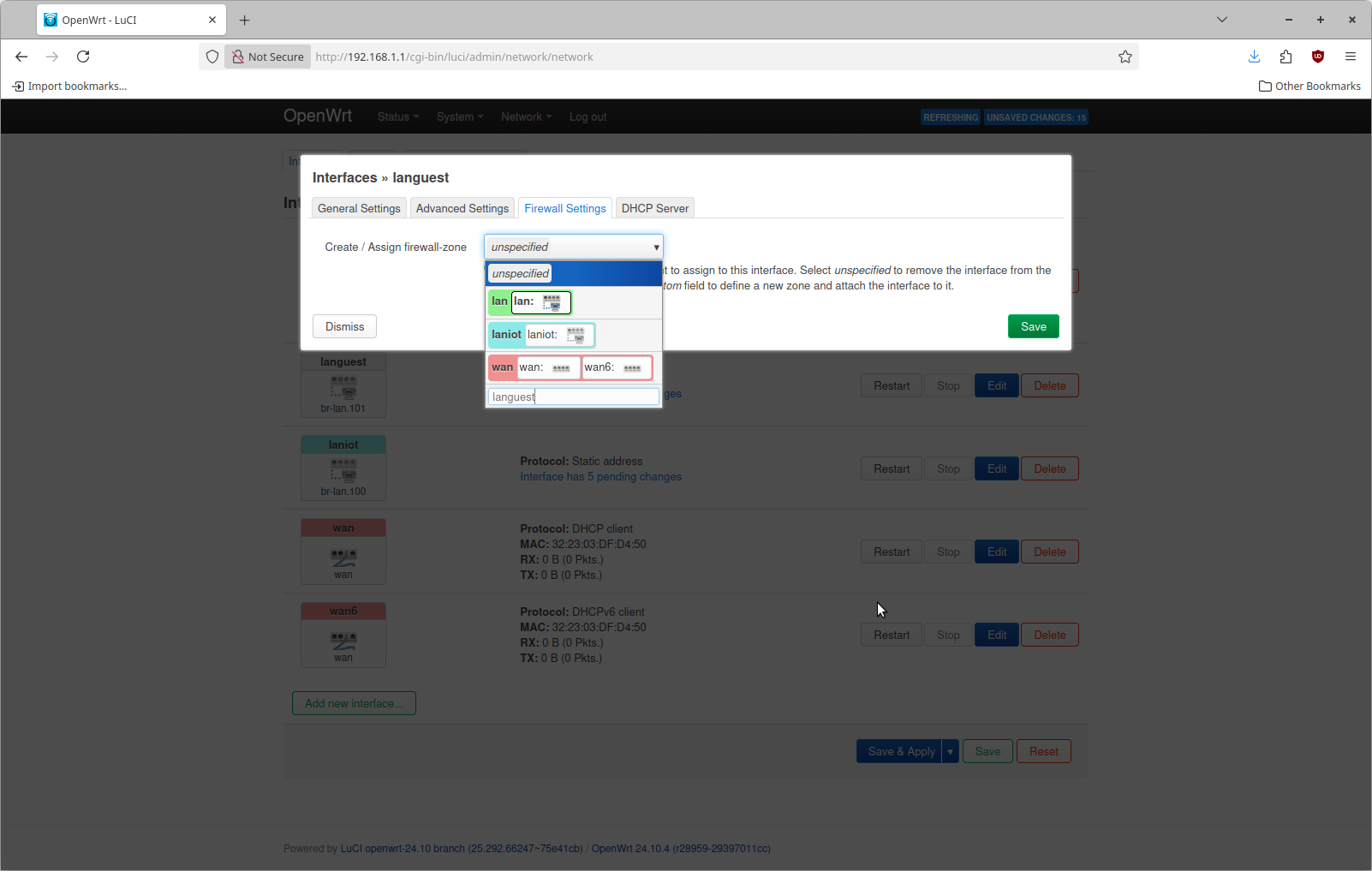
Within this dialog, select the Firewall Settings tab and specify to create a new firewall zone of laniot.
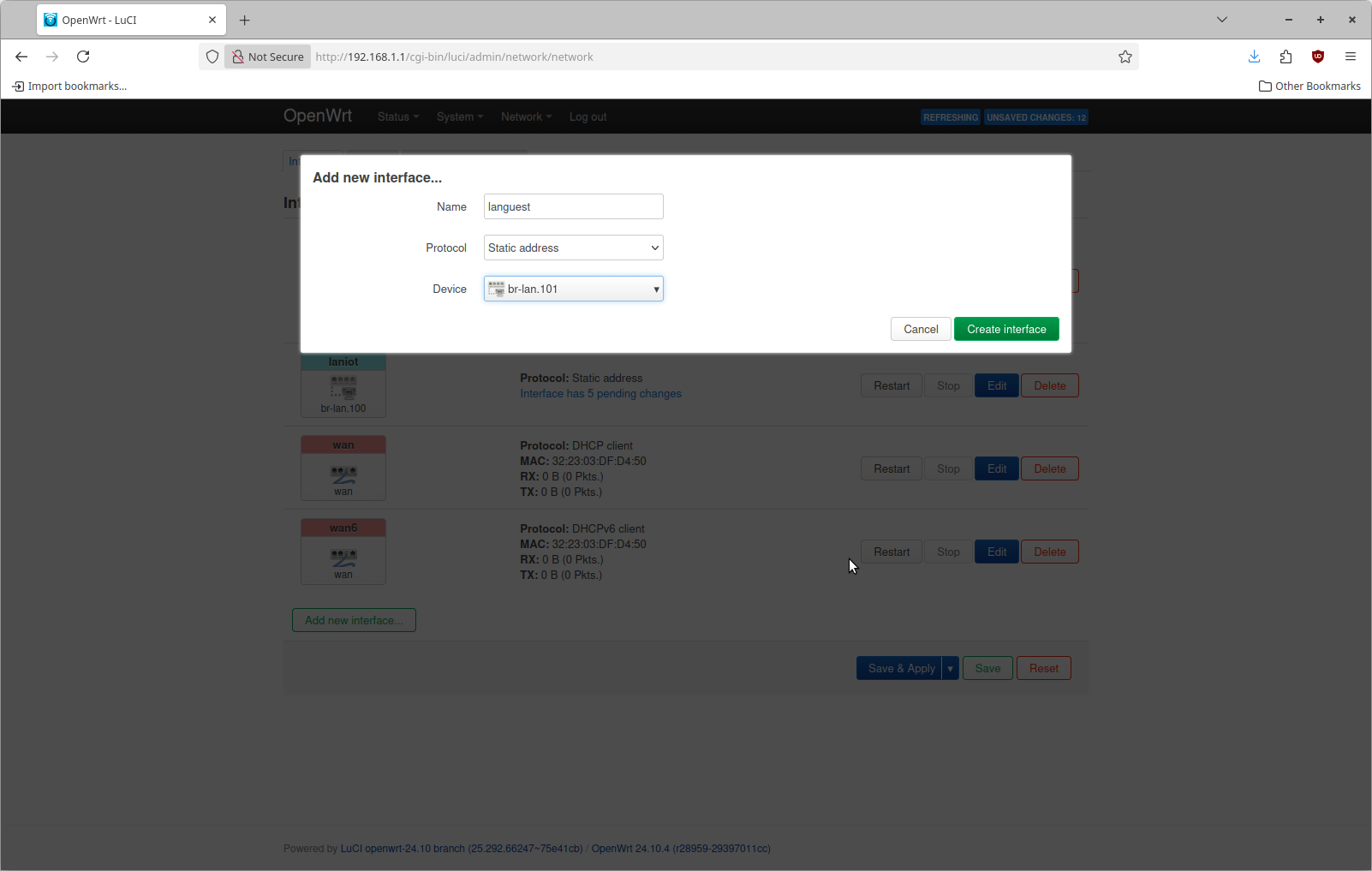
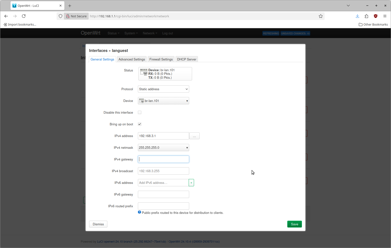
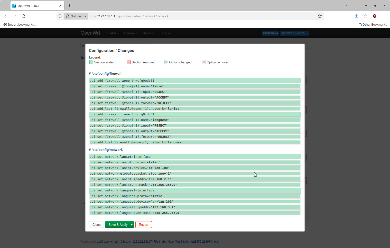
You can repeat these same steps to create the languest interface for VLAN 101.
Now save and apply this configuration change. It should look something like this
Step 3: Configure WiFi
By default OpenWrt does not enable the WiFi. This particular piece of hardware has 3 radios. I'm only going to use one of them. This is what the WiFi configuration page looks like by default.
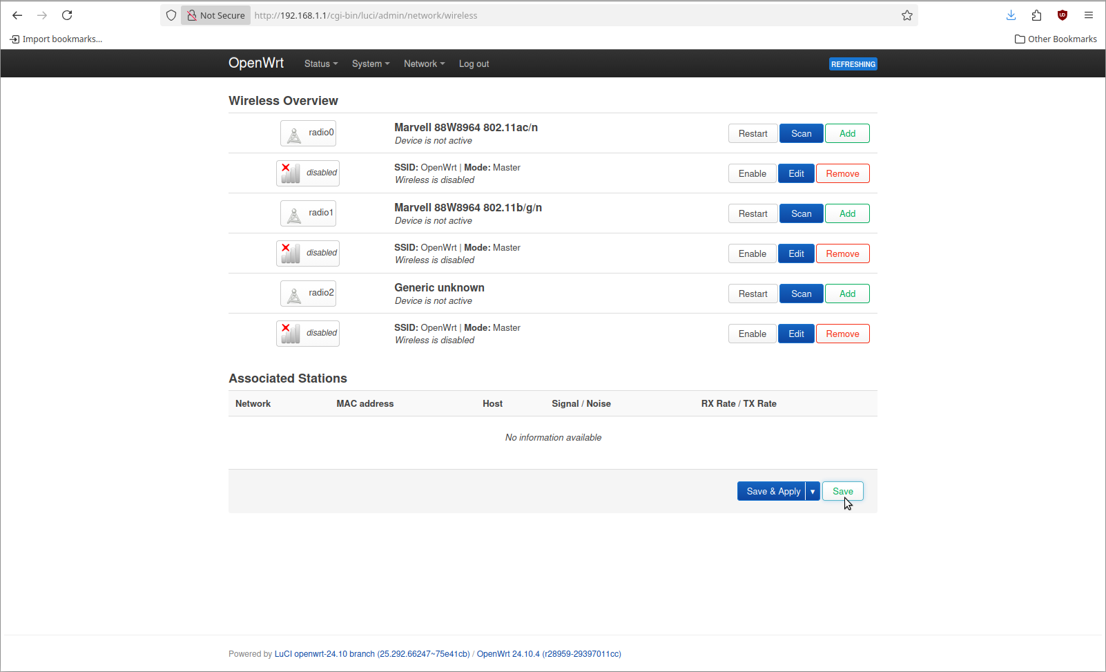
Now we can remove all configured SSIDs. This is done by clicking the Remove button beside each one.
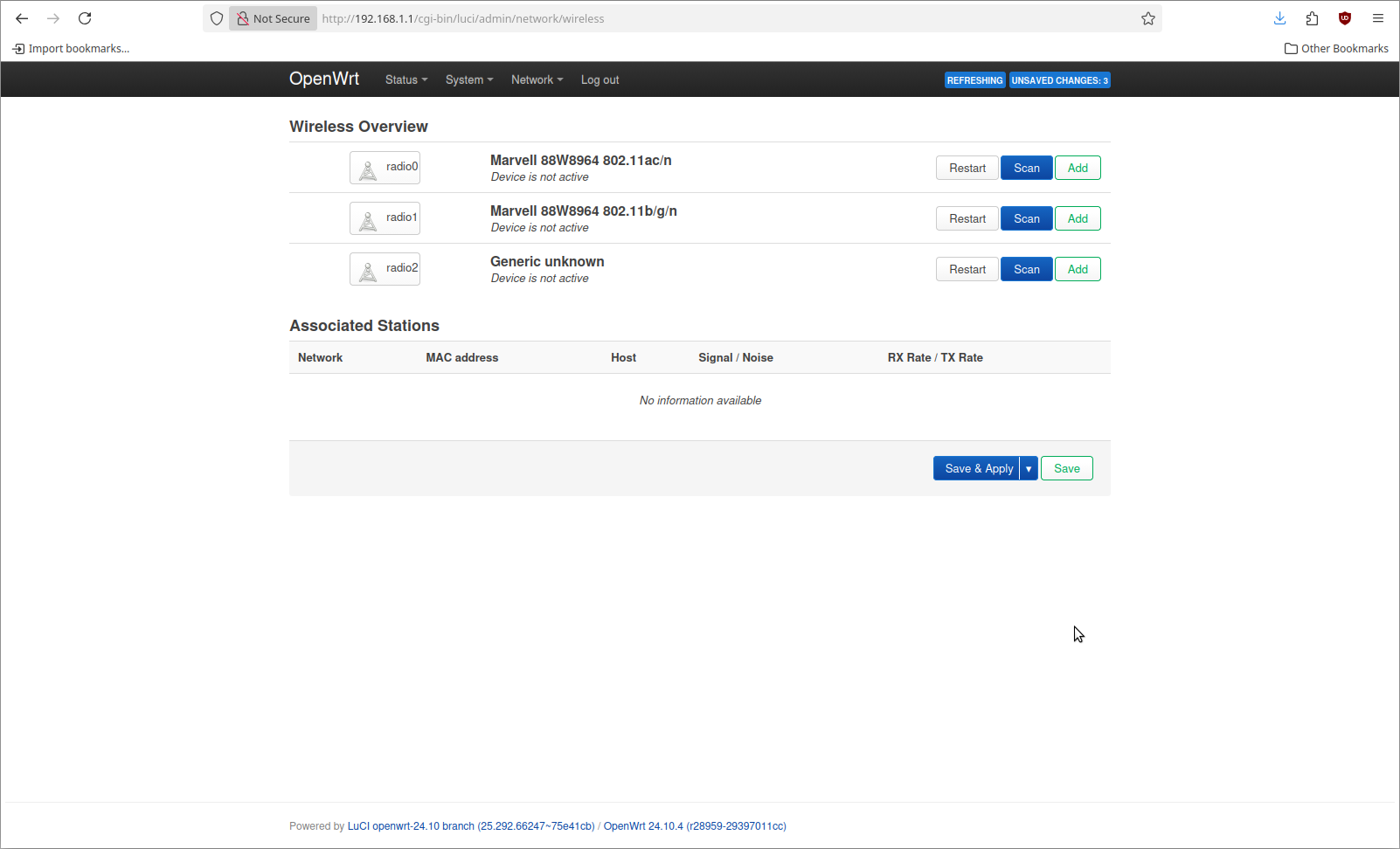
Now we can add 3 different WiFi networks. The steps for this are not any different than what would happen normally. The difference is in the Network selection under the Interface Configuration at the bottom
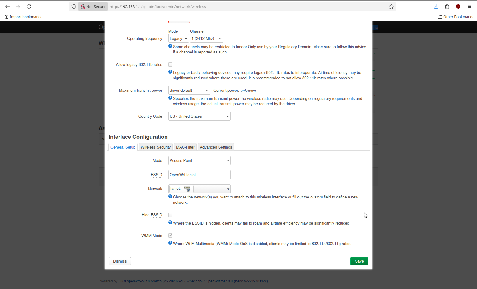
I added 3 different WiFi SSIDs that are named the same as the network they connect to. That looks lik this when I go to apply it.
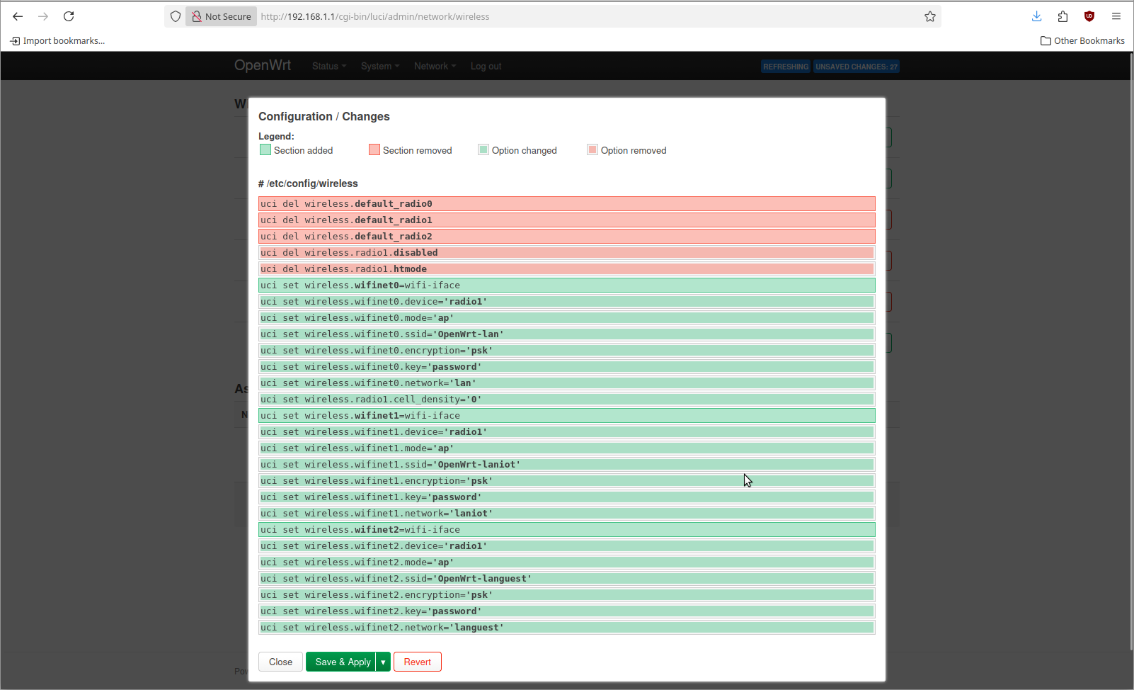
When you save & apply this you should be able to see 3 different WiFi networks using your wireless device.
Step 4: configure the firewall
The previous steps also created new firewall zones. Each firewall zone needs to have a configuration change applied. The default configuration looks like this
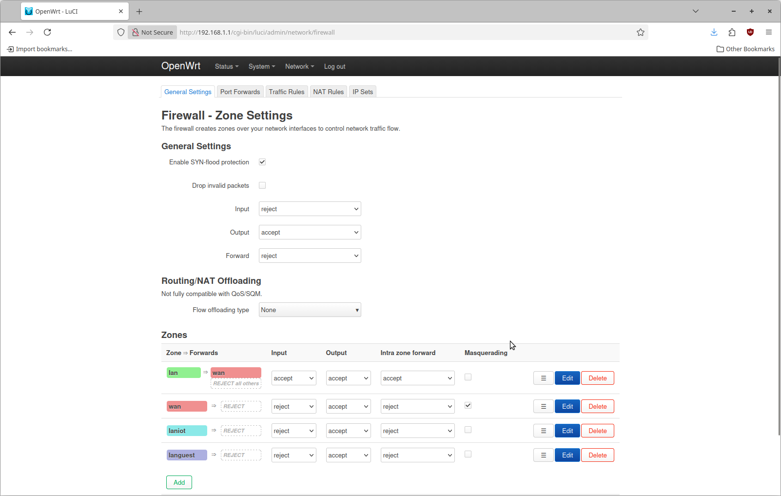
What needs to be changed is to set the input policy for the new laniot and languest firewall zones as accept. Then save and apply this change.
Validating this setup
In my case I have my computer plugged into the OpenWRT box directly. My computer has an IP of only 192.168.1.50 that was configured statically. I wanted to test that OpenWRT is doing what I wanted, so I used my laptop to test each WiFi SSID.
Testing the "lan" network
This was the easiest case to test. What I did was connected my laptop to the OpenWrt-lan wifi network then ping the IP of 192.168.1.50. On my workstation I was able to capture this packet.
$ tcpdump -e -n -v -i enp6s0 'inbound and icmp'
tcpdump: listening on enp6s0, link-type EN10MB (Ethernet), snapshot length 262144 bytes
18:48:21.982220 90:cc:df:f6:9d:cf > 58:47:ca:7b:d5:c6, ethertype IPv4 (0x0800), length 98: (tos 0x0, ttl 64, id 12799, offset 0, flags [DF], proto ICMP (1), length 84)
In this case the packet arrives at my workstation, untagged.
Testing the "laniot" network
I connected my laptop to the Openwrt-laniot network and then configured a static IP of 192.168.2.50. Then I ran ping 192.168.2.51. Since there is no actual device with that IP the ping is never sent. But I can see on my workstation the ARP packet trying to resolve that destination IP address
$ tcpdump -e -n -v -i enp6s0 'inbound and not tcp'
tcpdump: listening on enp6s0, link-type EN10MB (Ethernet), snapshot length 262144 bytes
18:55:57.943401 90:cc:df:f6:9d:cf > ff:ff:ff:ff:ff:ff, ethertype 802.1Q (0x8100), length 60: vlan 100, p 0, ethertype ARP (0x0806), Ethernet (len 6), IPv4 (len 4), Request who-has 192.168.2.51 tell 192.168.2.50, length 42
18:55:58.967832 90:cc:df:f6:9d:cf > ff:ff:ff:ff:ff:ff, ethertype 802.1Q (0x8100), length 60: vlan 100, p 0, ethertype ARP (0x0806), Ethernet (len 6), IPv4 (len 4), Request who-has 192.168.2.51 tell 192.168.2.50, length 42
18:55:59.991306 90:cc:df:f6:9d:cf > ff:ff:ff:ff:ff:ff, ethertype 802.1Q (0x8100), length 60: vlan 100, p 0, ethertype ARP (0x0806), Ethernet (len 6), IPv4 (len 4), Request who-has 192.168.2.51 tell 192.168.2.50, length 42
The packet arrives tagged with vlan 100.
Testing the "languest" network
I connected my laptop to the Openwrt-languest network then configured a static IP of 192.168.3.2. Then I ran ping 192.168.3.51. Since there is no actual device with that IP the ping is never sent. But I can see on my workstation the ARP packet trying to resolve that destination IP address
$ tcpdump -e -n -v -i enp6s0 'inbound and not tcp'
tcpdump: listening on enp6s0, link-type EN10MB (Ethernet), snapshot length 262144 bytes
18:59:23.640506 90:cc:df:f6:9d:cf > ff:ff:ff:ff:ff:ff, ethertype 802.1Q (0x8100), length 60: vlan 101, p 0, ethertype ARP (0x0806), Ethernet (len 6), IPv4 (len 4), Request who-has 192.168.3.51 tell 192.168.3.2, length 42
18:59:24.664998 90:cc:df:f6:9d:cf > ff:ff:ff:ff:ff:ff, ethertype 802.1Q (0x8100), length 60: vlan 101, p 0, ethertype ARP (0x0806), Ethernet (len 6), IPv4 (len 4), Request who-has 192.168.3.51 tell 192.168.3.2, length 42
18:59:25.688521
The packet arrives tagged with vlan 101.