Ignition only wiring harness for 1981 Yamaha XT250
- Saturday November 19 2016
- electrical ignition
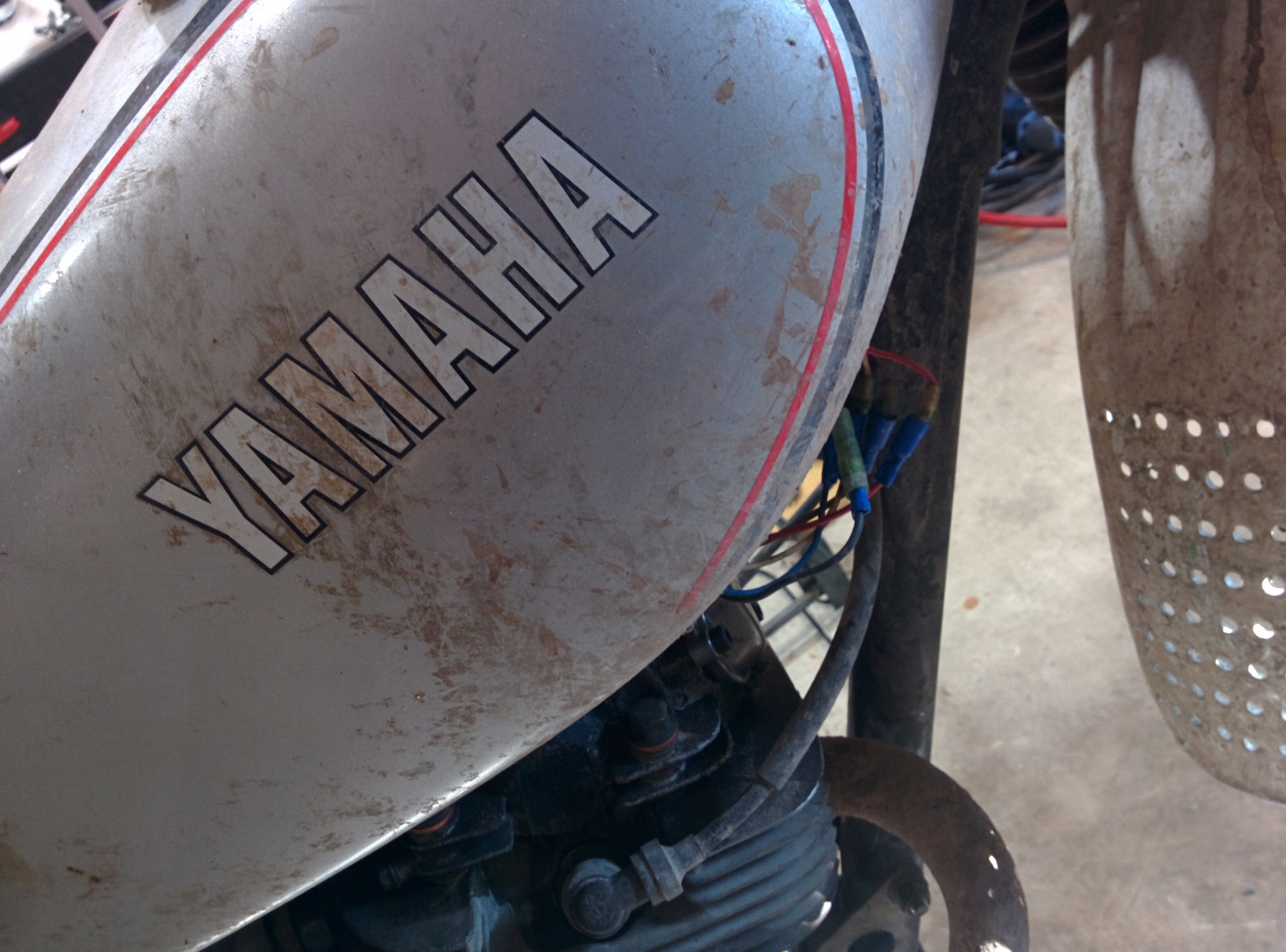
The 1981 Yamaha XT250H is originally sold as a dual spor motorcyclet. It's got huge blinkers, a head light, tail lamp, etc. I'm not currently using any of that equipment since I am using the vehicle off road only. The original wiring harness is quite large as a result of all the lamps. I want to eliminate the original wiring harness to reduce weight and clutter on the motorcycle.
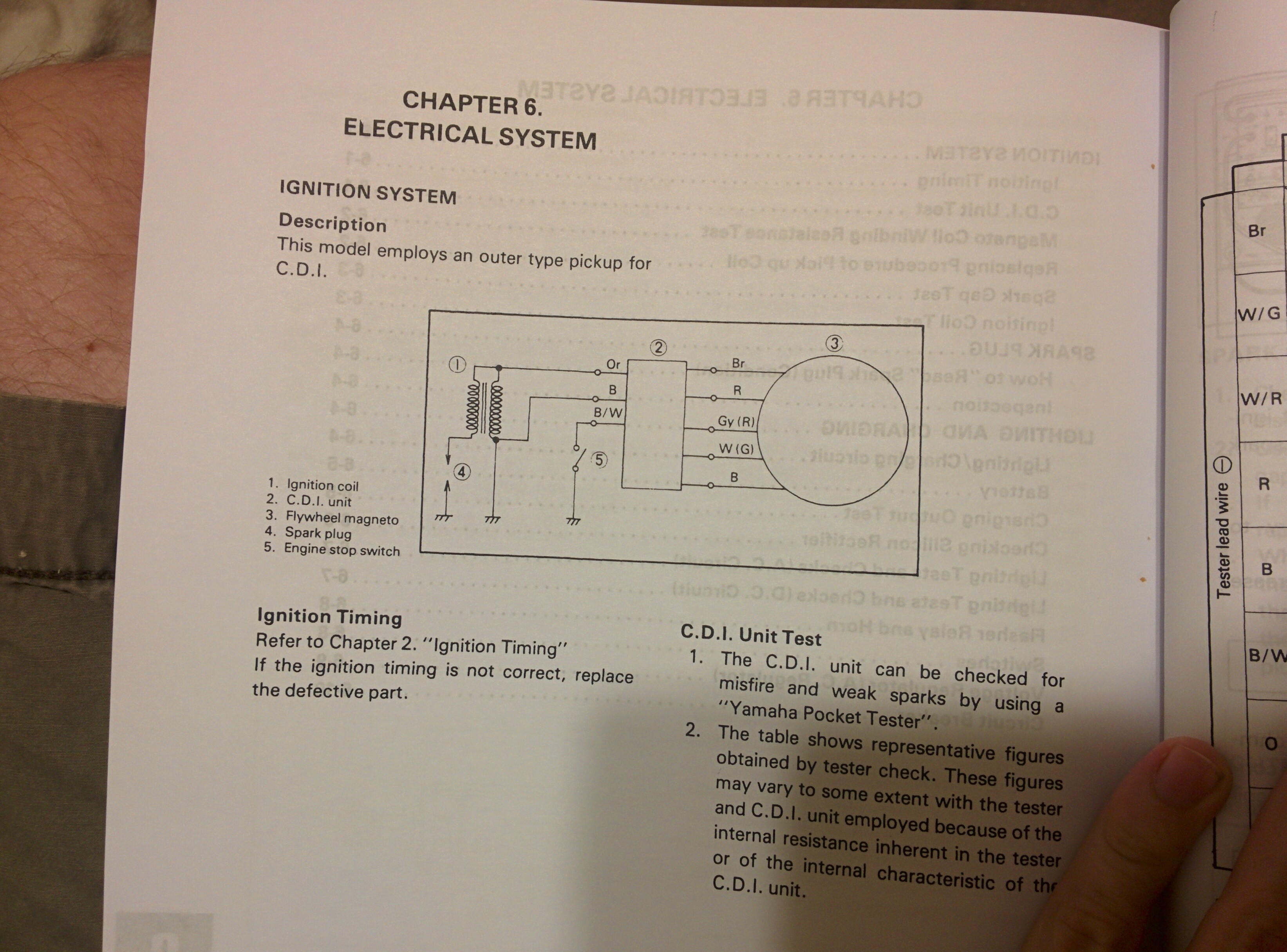
The ignition system on this motorcycle is a CDI unit. It consists of 5 components
- The magneto coil
- The pickup coil
- The CDI unit
- The ignition coil
- The spark plug
The way this system works is the magneto coil provides alternating current power to the CDI unit. The CDI contains components that allow it to use this power to drive the ingition coil. The ignition coil converts a low voltage, high current pulse into a high voltage, low current pulse. This pulse travels to the spark plug, which can ignite the air and fuel mixture in the cylinder. For all of this to happen at the correct time, the CDI unit must know when to fire. The pickup coil provides this signal to the CDI unit.
Inside the left hand side of the motorcycle is the stator unit. It is covered by the rotor normally. The stator contains 3 coils. They are from left to right in the photo
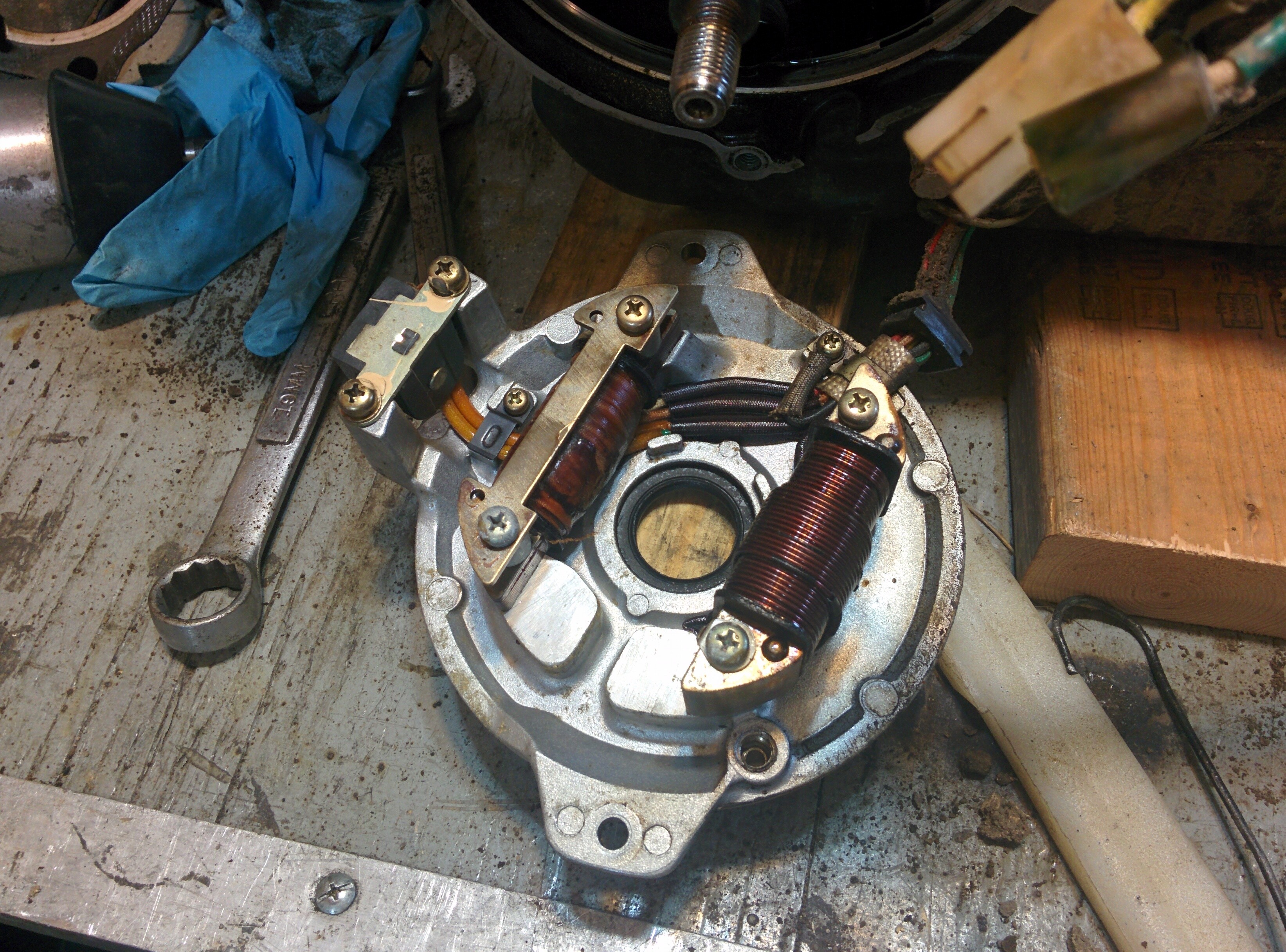
- The pickup coil
- The magneto coil
- The lighting coil
The lighting coil isn't relevant for the ignition circuit and can be ignored. There are a total of 8 wires that come out of the electrical harness from the engine. The wires on my motorcycle appear to be cotton insulated. It was quite difficult to tell what colors the wires were, but rubbing them with motor oil seemed to help. The cotton is dyed a certain color, but the wire inside is a different color. The color of the cotton is what matters. There are 8 wires that come out of the wiring harness
- Yellow - lighting coil high
- Green - lighting coil low
- Blue - oil level sensor
- Black - engine ground
- Brown - magneto coil
- Red - magneto coil
- White with red plastic - pickup coil
- White with green plastic - pickup coil
The first 3 wires are contained within a 4 pin plug, that only uses 3 pins. They are only for the lighting circuit, so you can ignore them.
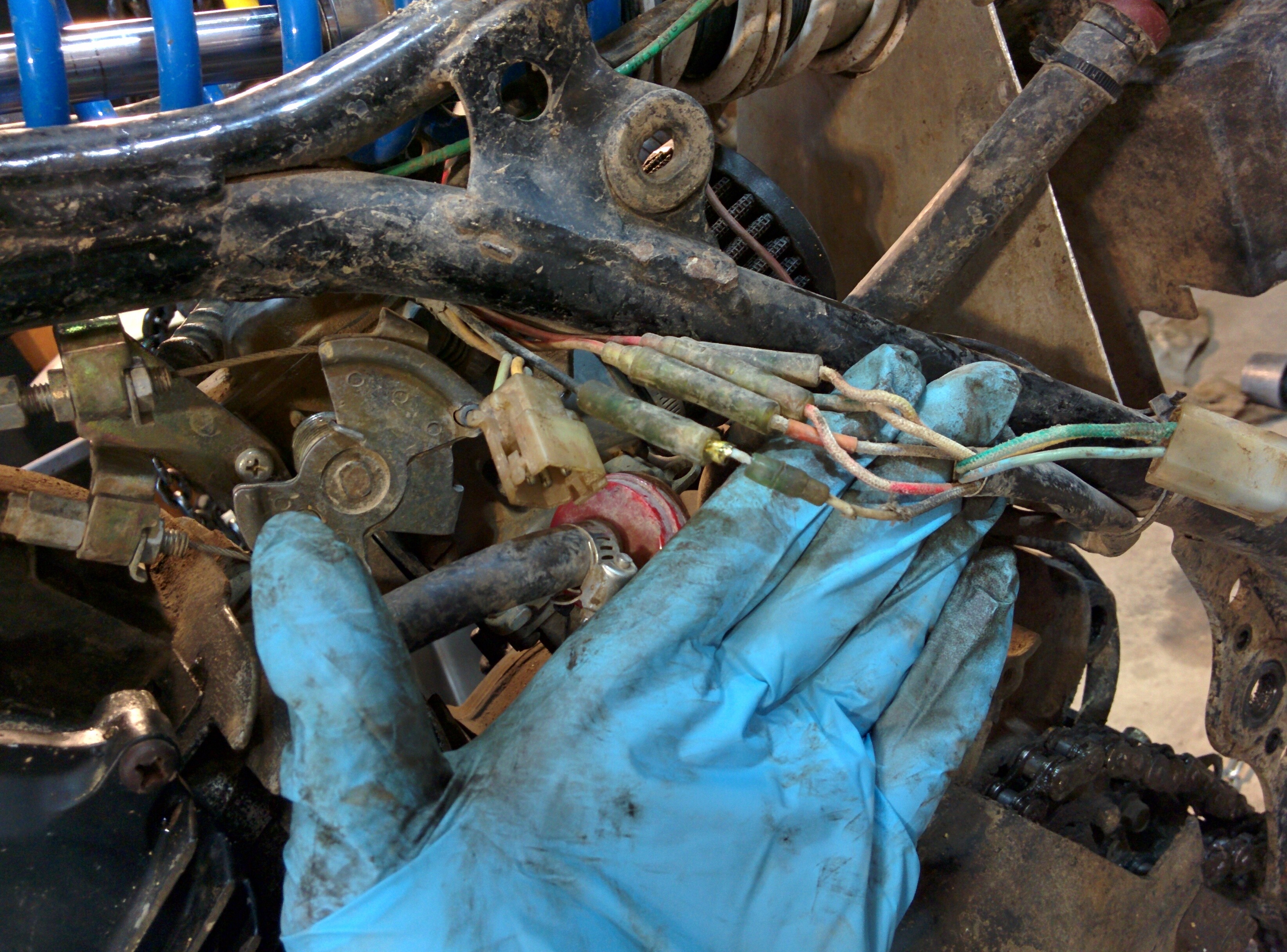
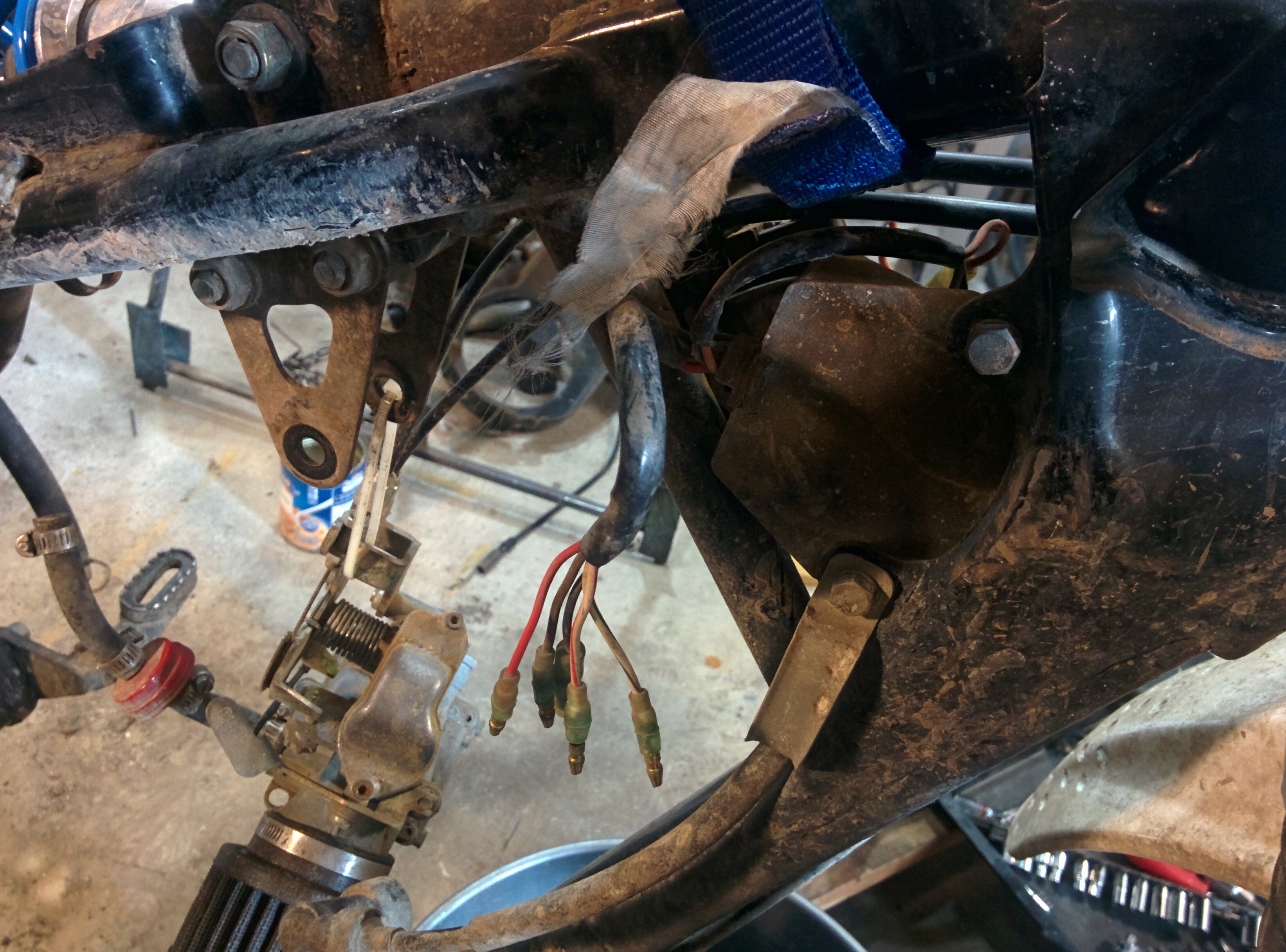
All the other wires use bullet connectors. They ones on the stator were filled with dirt, so I just cut through the bullet connector.
The last two wires are pecuilar, because the cotton is actually white in color. There is small piece of colored plastic around the wire that helps identify them. The wire with the red plastic connects to the white wire with red stripe on the harness. The wire with the green plastic connects to the white wire with the green stripe on the harness.
The coloring is identical at the CDI. The white-green, white-red, red, brown, and black wires go to the CDI unit. The CDI unit has 3 additional wires. They are
- Orange - Ignition coil positive
- Black - Ignition coil ground
- Black with white stripe - kill switch
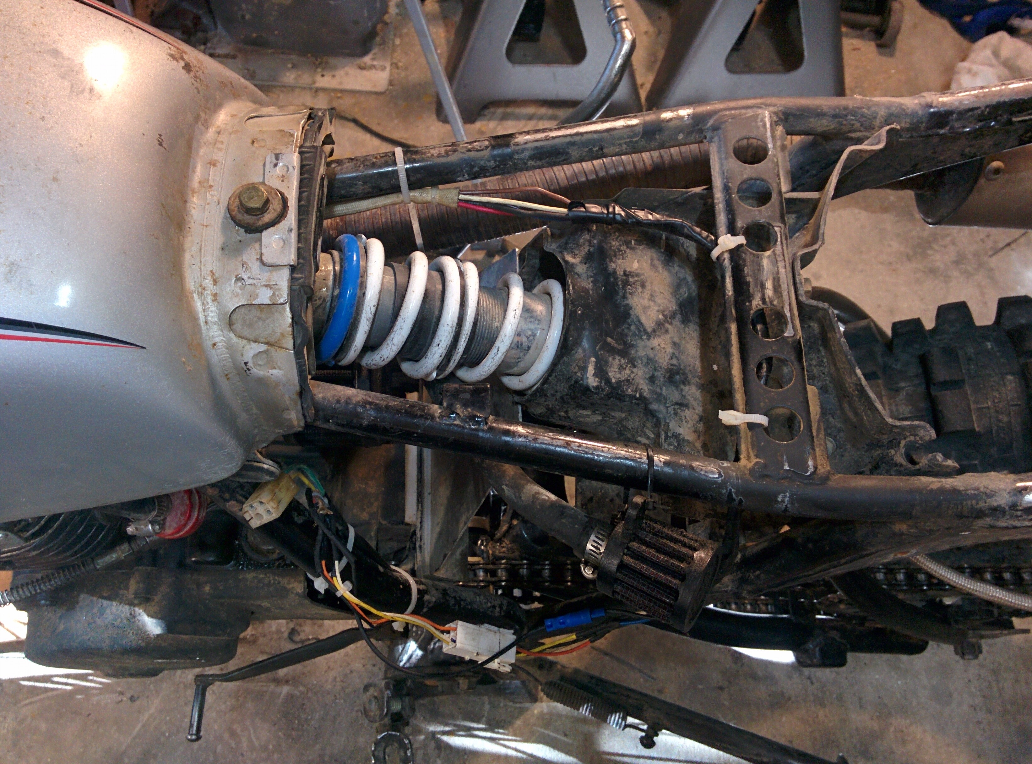
The CDI unit is mounted beside the ignition coil. So there is no real need for a harness to connect those wires together. The orange wire goes directly into the wire on the ignition coil. The black wire needs to connect to the metal body of the ignition coil. I made up a short jumper with a ring terminal and a bullet connector to connect those together.
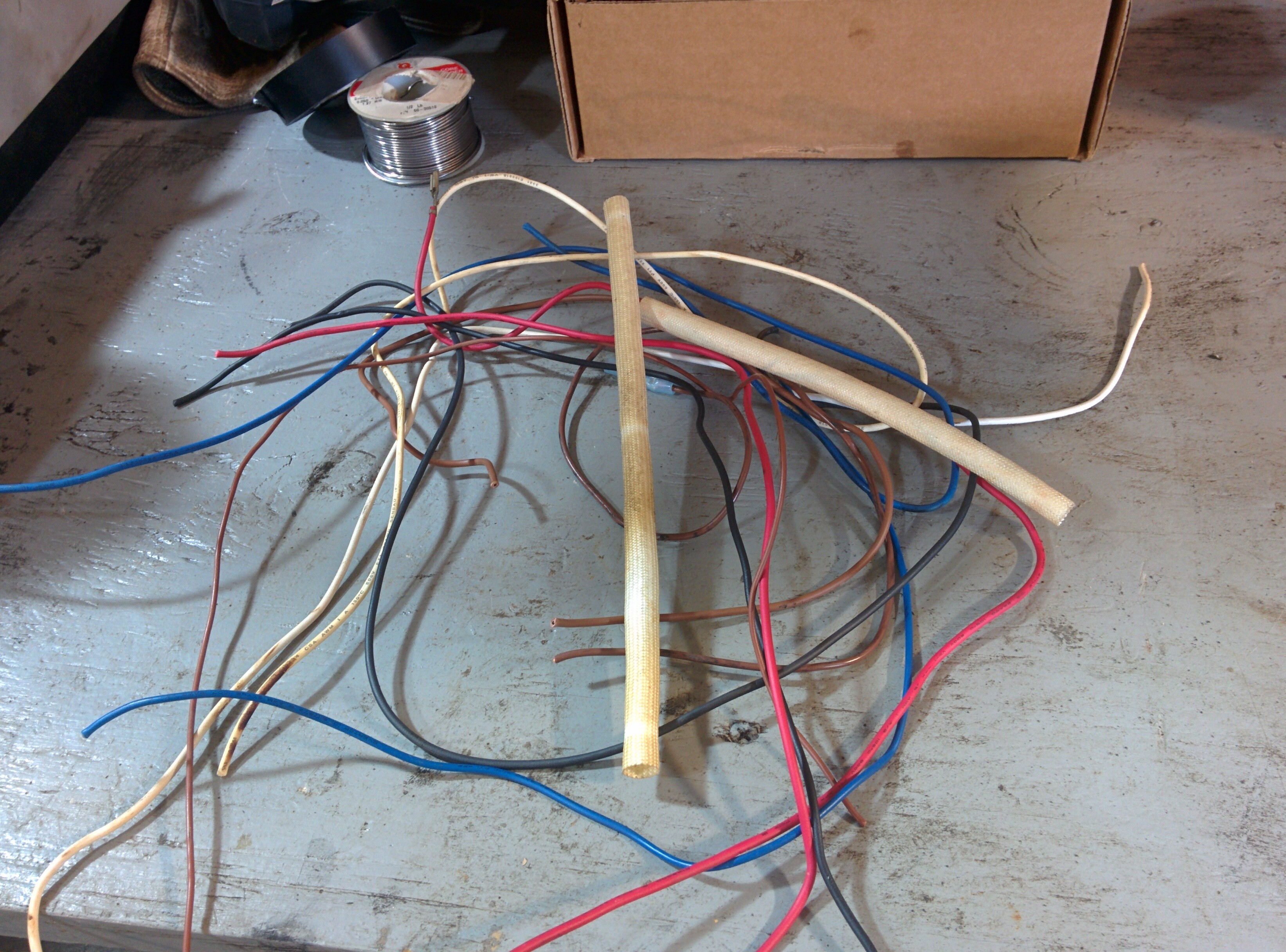
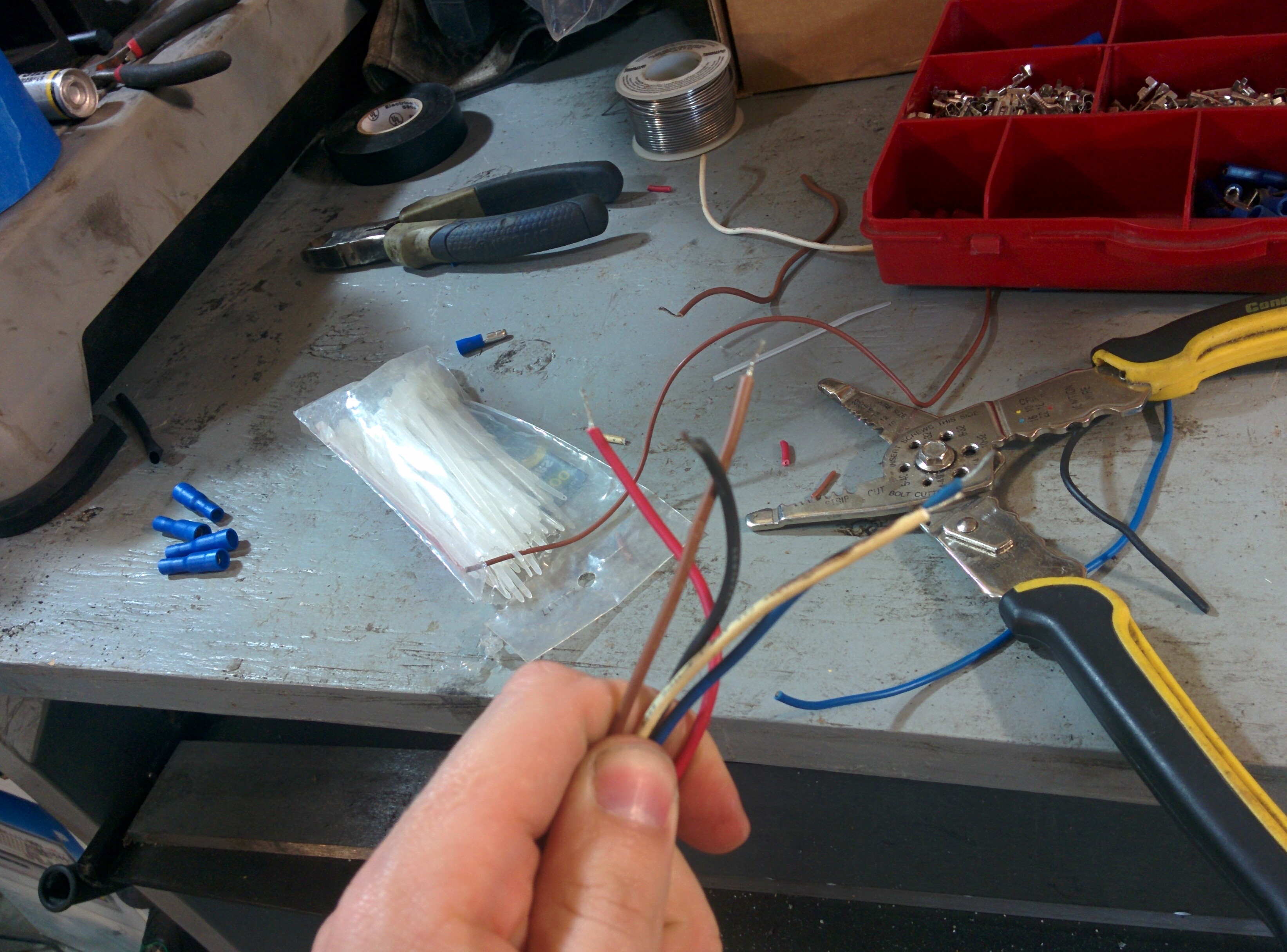
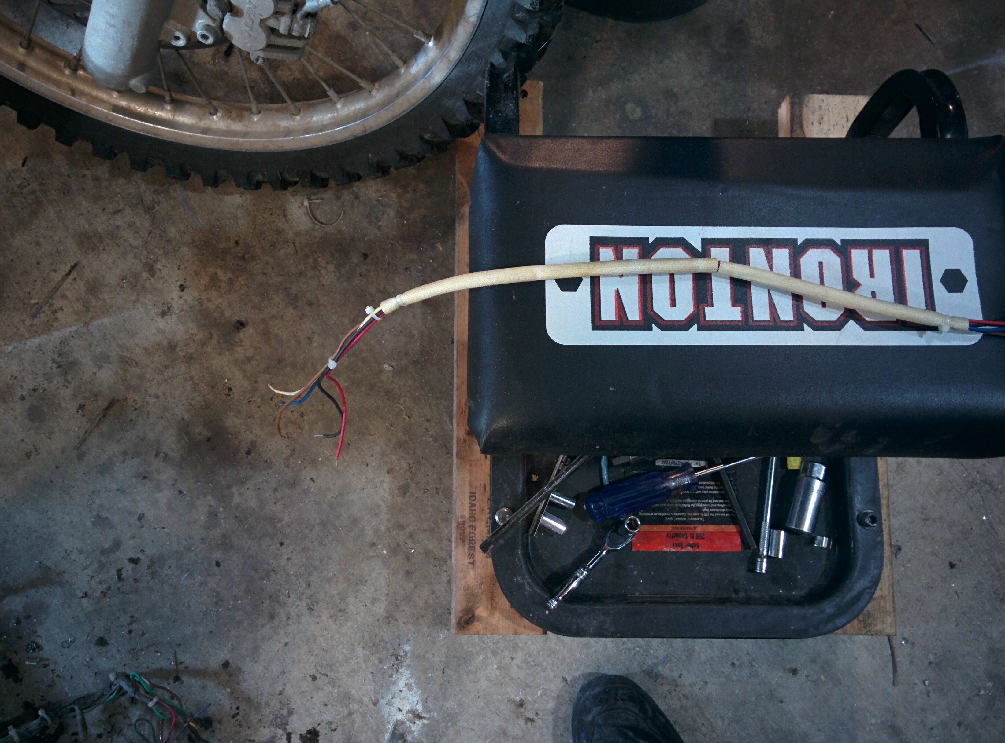
I figured I needed 35 inches of wire to connect the CDI unit back to the stator. This turned out to be a bit long, but worked OK. I don't really keep wire around so I gathered up some wire from wiring harnesses I removed from microwave ovens. As a plus, most of these wiring harnesses had some fiberglass sheathing that I reused to create a sheath for the harness. I also found a 4 pin connector in a wiring harness. So I put that on the coils coming from the stator. The ground I put a new bullet connector on. Anywhere I had to splice wire together I solder and heatshrink. I'm not sure how long all this will last, but it didn't really cost me anything and I had no other materials on hand. I covered the remainder of the wiring harness with black electrical tape.
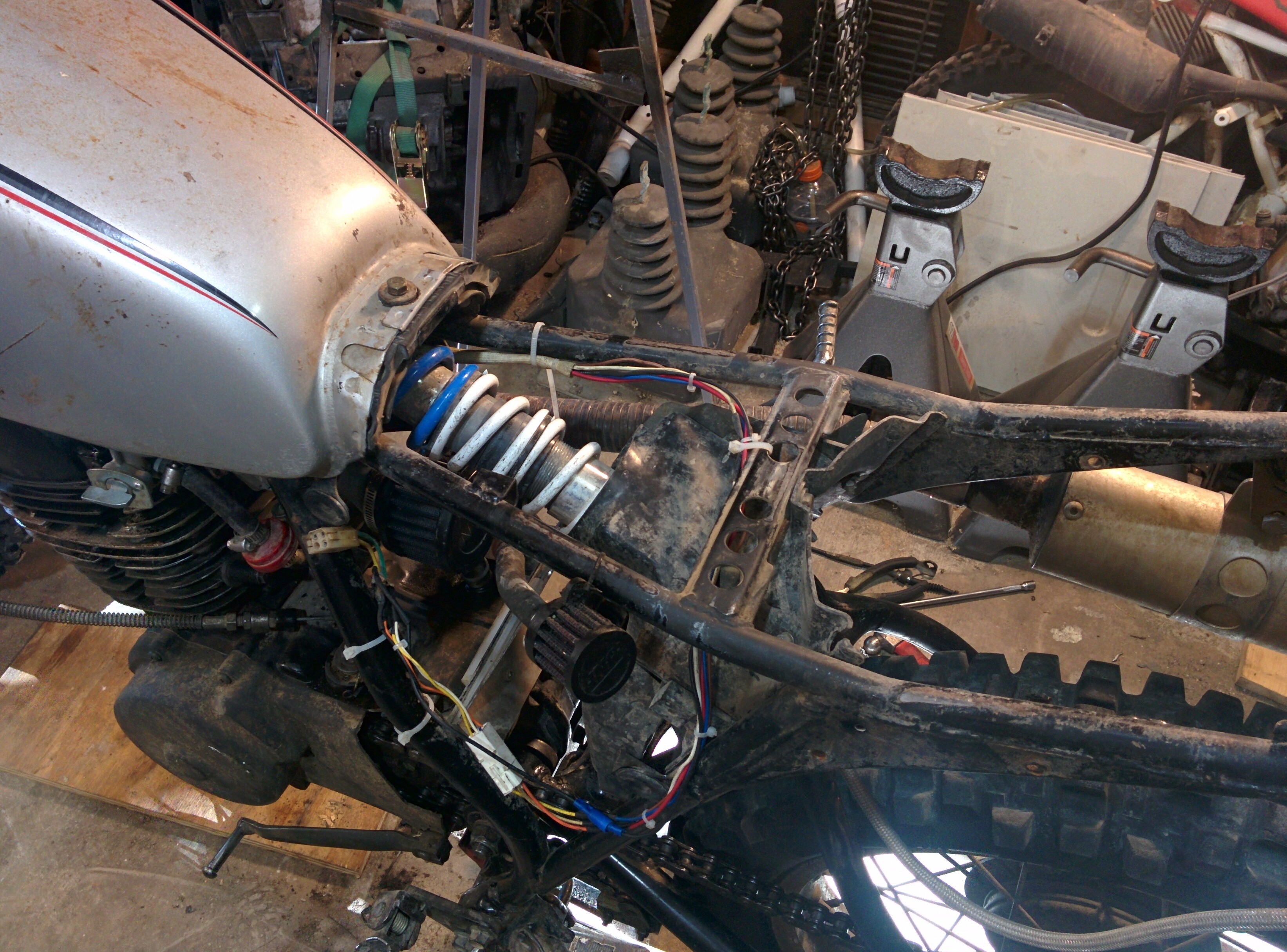
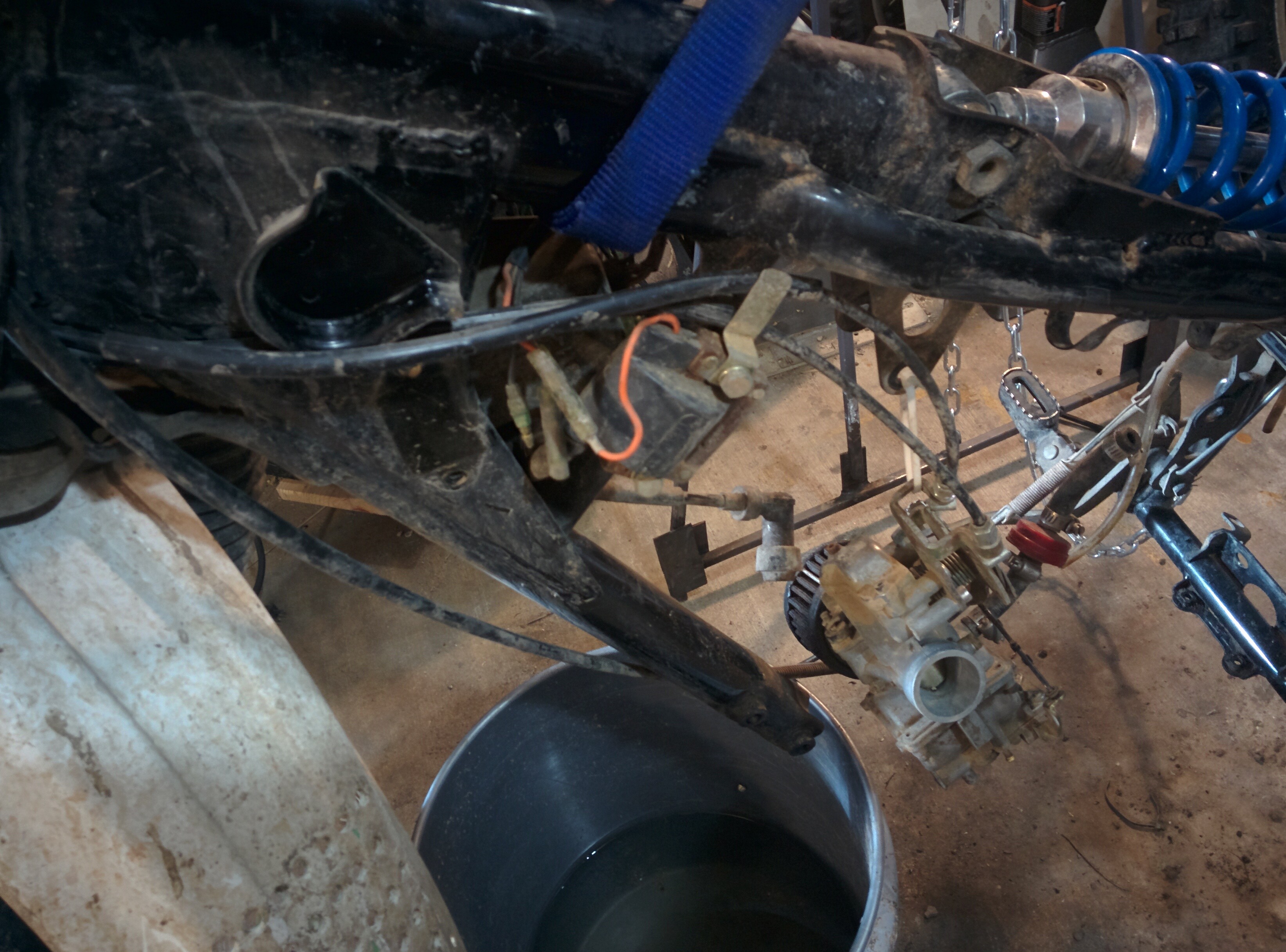
One of the very annoying things about the original wiring harness was the fact that the connectors were directly in the way of the choke on the carb. I took the opportunity to route the harness behind the carb and over the shock to try and keep them out of the way.