Portable vertical antenna for amateur radio
This is my portable vertical antenna system for HF radio. This is meant as an assembly guide, but not a complete set of plans. The final product you build likely is going to be different based off the components you have available.
The prototype I built earlier this year, hastily constructed and far too heavy
The revised version construction is described here
- Requirements
- Construction
- Transporting the antenna base and tuner
- Setup and tuning the antenna
- Testing
Requirements
For this project I had number of requirements for the finished product
- Backpack portable
- Lightweight
- Usable 40 meters to 6 meters
- Assemble and setup without tools
- Relatively durable
- Cheaper to fabricate than commercially available portable antennas
The design I chose is based off being easy to fabricate and the availability of whip antennas that are approximately 5.5m long.
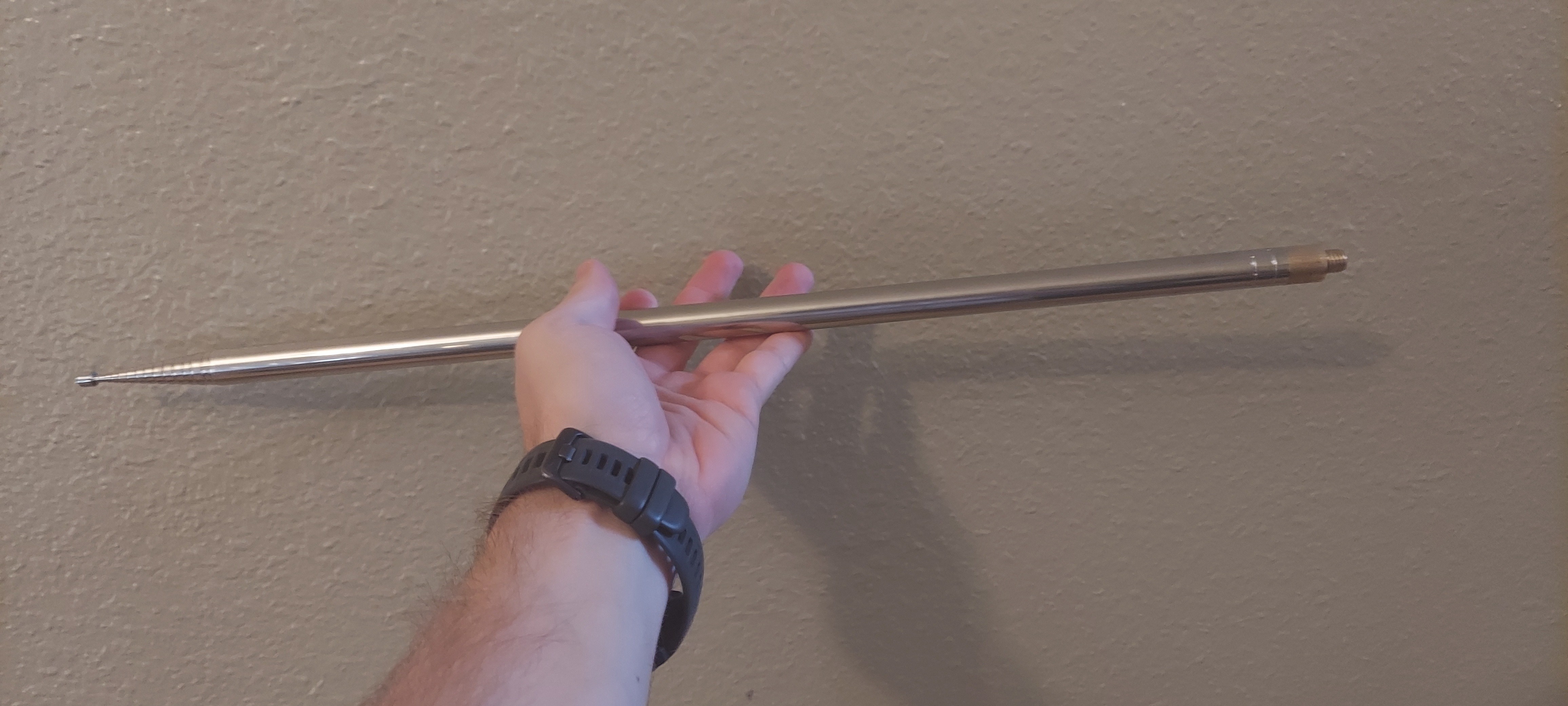
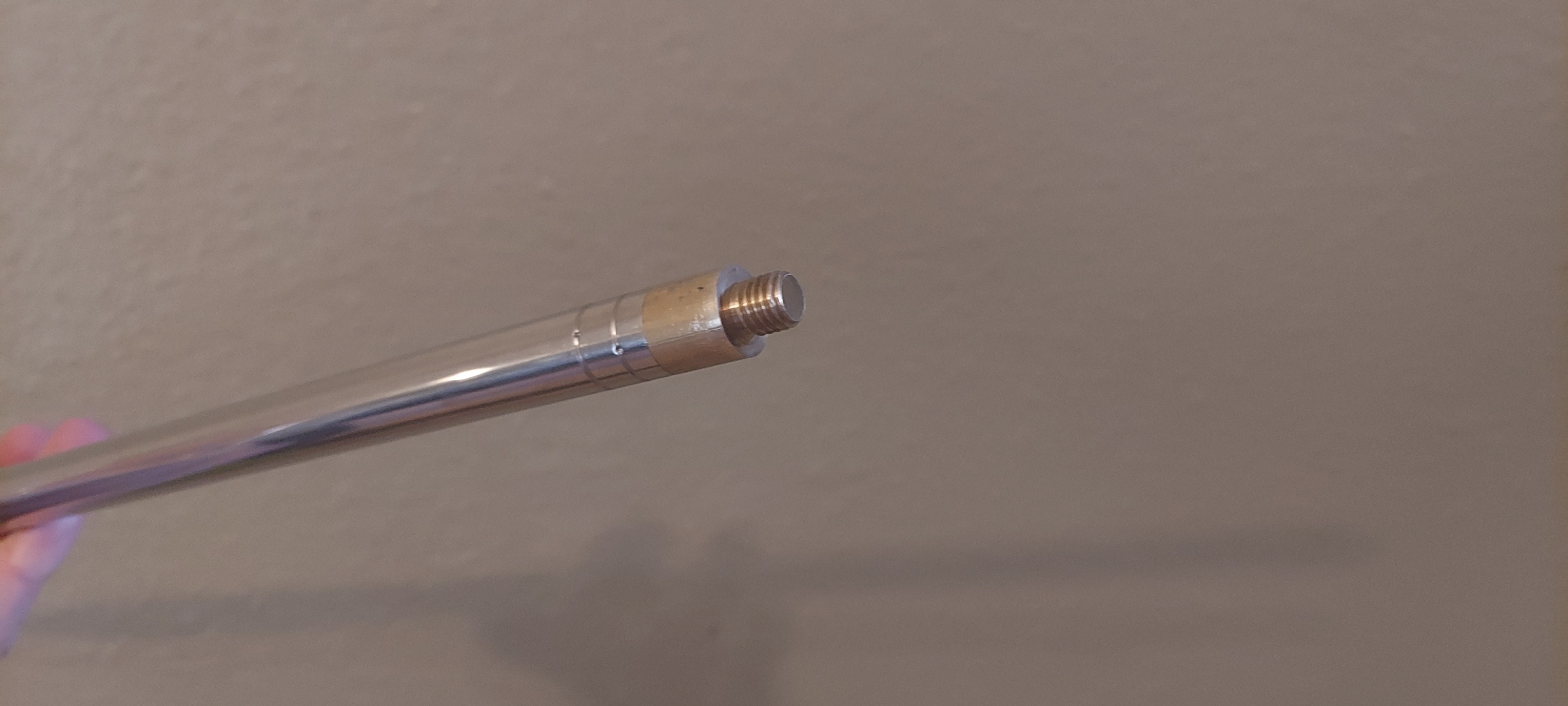
This whip antenna was purchased based off AliExpress for around $30 shipped to me. If you search for "BD7IBI whip" you can find them. The base is threaded with an M10-1.5 male thread made of what appears to be brass. I also have a fiberglass whip designed for 11 meters that breaks down into portable sections with the same thread on it.
Antenna tuner L-network
In order to be able to use frequencies longer than the electrical length of the whip I needed to incorporate some kind of antenna tuner to match the impedance of the antenna to the impedance of the radio transceiver. To do this I decided to incorporate into my design an L-Network tuner.
There are technically 8 variations of the L-Network as explained here. My design only allows two variations to be utilized which are the C-Parallel, L-Series and the L-Series, C-Paralell configuration. You could reconfigure this design into being any of the above 8 however. A more practical description of the four configurations in common use is found here
These are the two configurations possible with this setup.
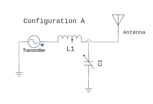
For matching antenna impedance above 50 ohms
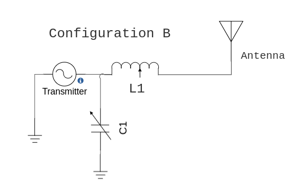
For matching antenna impedance below 50 ohms
For a physically short antenna the impedance is usually less than 50 ohms, configuration B is used. Using configuration A is only needed in circumstances when a physically short antenna is used in proximity to conductive objects like a metal building, where the antenna impedance can be unexpectedly high.
For frequencies where the antenna is longer than 1/4 wavelength I can just collapse the whip to get to get to approximately 50 ohms. The inductor is shorted completely so it is out of circuit and both ends of the capacitor are connected to ground so it has no effect on the circuit.
Cost vs. performance
I'd like to point out this kind of setup is not going to outperform high end portable antenna setups like a Buddipole. A dipole style antenna that is high above the ground is always going to outperform a ground mounted vertical. Compared to a vertical it is by definition highly directional. It also should suffer no ground losses if at least 0.62 wavelengths above the terrain.
At the time of writing the basic Buddipole is $279. I spent less than $100 assembling this unit.
Construction
Construction of this project involved many different tools and materials. I've tried to list everything here.
Materials
- 1 inch 1/8th thick steel L-channel
- 1/4 inch HDPE sheet
- 1-1/4 inch 1/8th thick steel flat bar
- M10 nut - pitch TBD
- 1/2-13 nuts
- 1/2-13 bolts 3/4 inch long
- 1/4 inch steel rod, at least two 10 inch secionts
- T200-6 iron powder toroid from Micrometals
- BNC panel mount connector
- 22 awg magnet wire
- 22 awg bare wire
- copper plated alligator clips (6x)
- solder
- 10-24 machine screws
- 8-32 machine screws
- 6-32 machine screws
- Zip ties
- short pieces of insulated wire
- variable air capacitor (at least 150 pF, up to 1000 pF is OK)
- knob for variable air capacitor
Material notes
HDPE sheet: I buy new pieces of HDPE sheet from industrial suppliers. If you like making stuff from HDPE this is a great choice. If you are just making a small project just go to the cheapest store near you and buy an HDPE cutting sheet. It's essentially the same material and can cost under $5 in some cases.
Iron powder toroid: The only US manufacturer of such materials with known specifications is Micrometals. I do not think Micrometals sells small quantities to individuals. I searched around and found someone selling Micrometals products in single quantities on Amazon. Don't waste your time with "iron powder" toroids from AliExpress. Those are all truly iron powder but given that there is no materials data sheet available it is a complete waste of time and money
RF connector: You may use any RF connector you wish, but BNC is always my preferred connector for portable operation below 500 MHz.
Tools
- welding machine
- drill with drill bits for metal
- hacksaw
- table saw
- razor blade scraper
- soldering iron
- C-Clamps
- wire clippers
- wire brush
- metal file
- bench grinder (can use the metal file instead if you have lots of time)
drill bits needed
- 1/2 inch
- 1/16 inch
- 1/4 inch
- 3/8 inch
- 7/32 inch
Making the mounting spikes
In order to make the mounting spikes I welded the steel rod directly to the head of a 1/2-13 bolt. These are used to stabilize the antenna system in the ground. You might notice I am using 3/8th steel bar in these photos. It is far too large. The spikes are much too heavy and don't go into hard ground readily. 1/4 inch round bar is definitely the correct choice here.
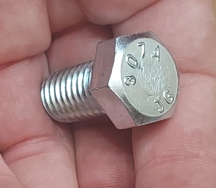
Start with a brand new bolt
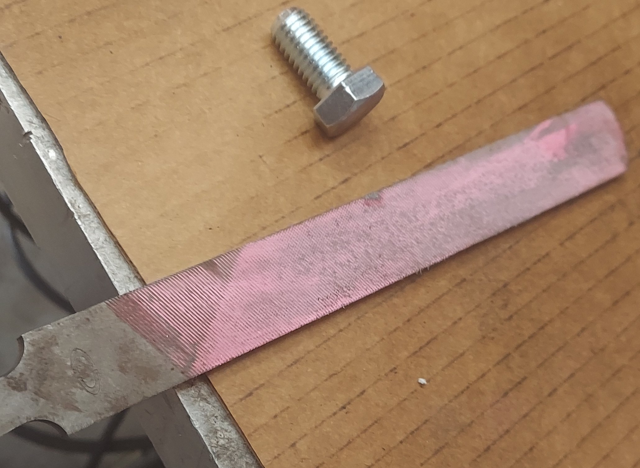
Using a large file remove the plating and the lettering from the top of the bolt
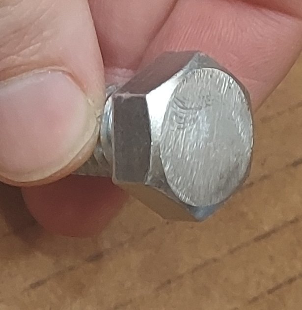
The top of the bolt should be smooth and clean afterwards
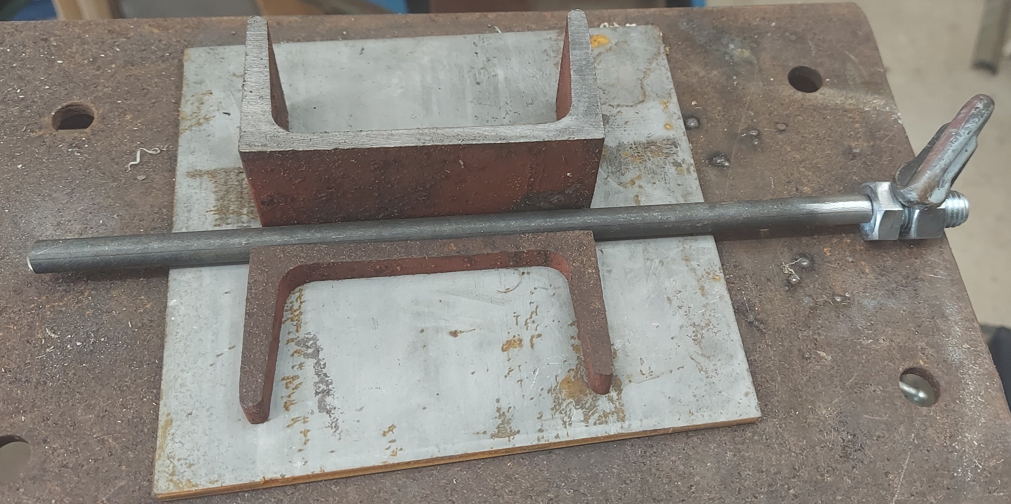
Place a nut on the bolt, then use clamps and other material to hold the parts in place
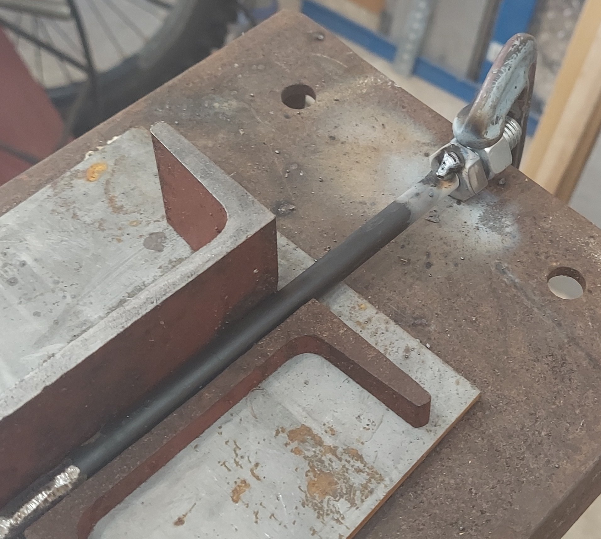
Any 3 small welds joining the bolt to the rod is acceptable
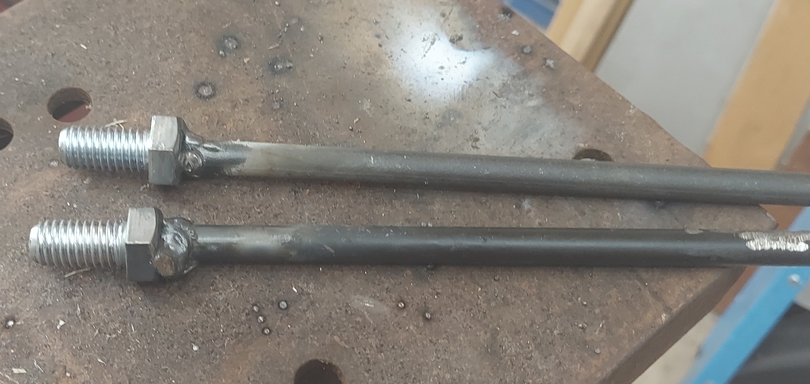
The completed product is not very pretty but functional
Making the mounting bracket
The mounting bracket consists of a section of 1 inch L-Channel that is 3 inches long. There are a few holes that need to be drilled into it. The purpose of the mounting bracket is to connect the plastic baseplate to the mounting spikes mechanically. It also gets used a as mounting point for the BNC connector. After cutting the L-Channel to length, deburr the edges with the bench grinder.
Looking at it closely, this piece of material is actually slighter larger than 1 inch in diameter. This came from my scrap pile and I am relatively certain it is some sort of metric dimensioned material. It doesn't really matter, if you have a similar sized piece of material it should be fine.
The material is cut to length and two 7/32 holes are drilled in each end
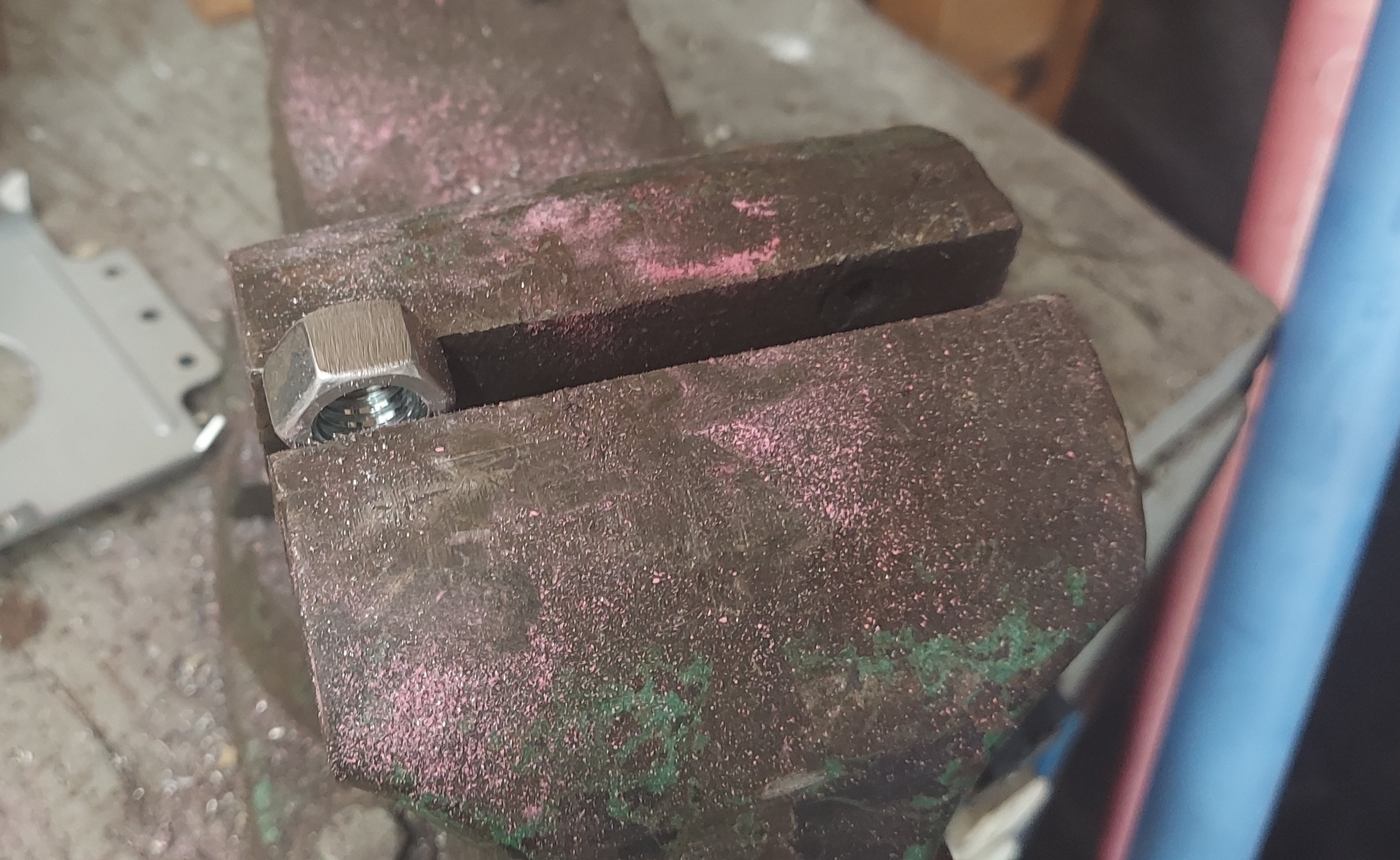
Two of the 1/2-13 nuts need the plating removed from one side of the hex
The pieces are clamped together with the bare sides of the nuts against the steel, then welded. Scrap material is used as a shim to orient everything correctly
The nuts only need a small amount of weld to hold them in place
A 3/8 hole is drilled off center for the BNC connector
Making the antenna mounting post
The antenna mounting post is made by welding together an M10-1.5 and a piece of flat steel plate drilled to accept it. The nut used is a flange nut meaning it has plenty of surface area to weld to. The nut is upside down when it is actually in use.
Alternatively you could get a thick section of metal, drill it out and tap it for M10-1.5. I don't have the needed material or tools for that and it seemed like more effort than it was worth.
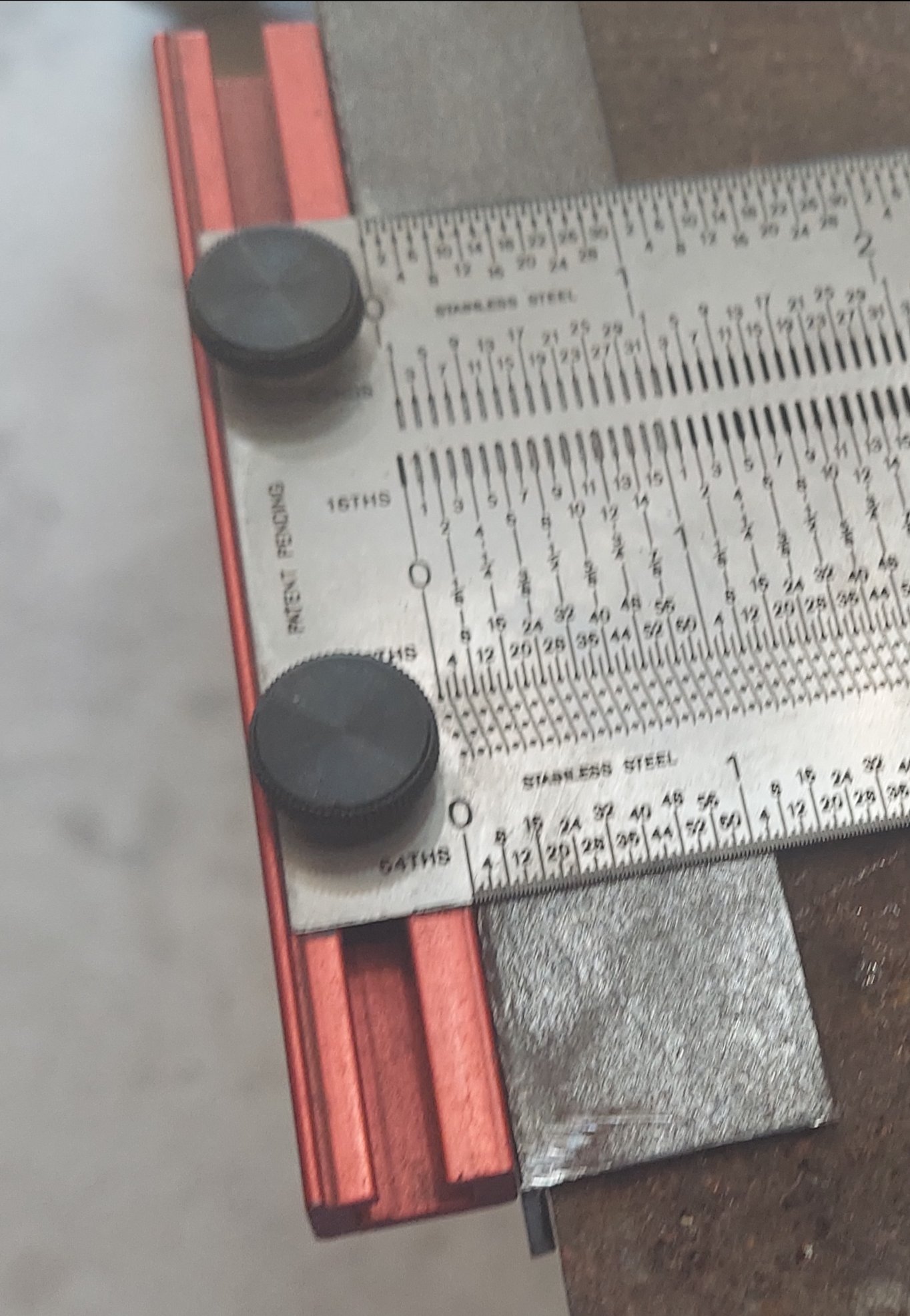
Start with a piece of 1-1/4 inch wide steel plate that is 1-3/4 inches long
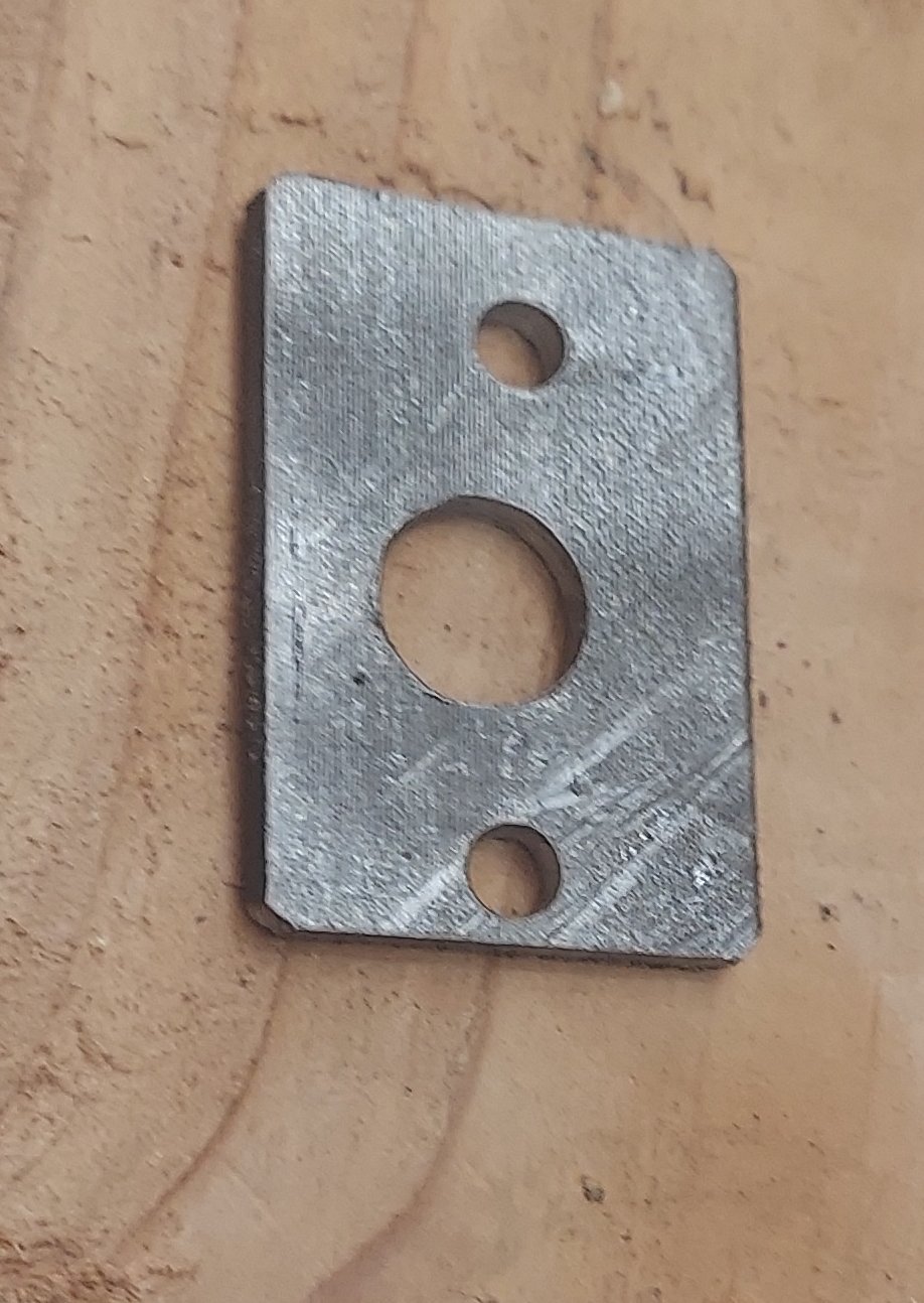
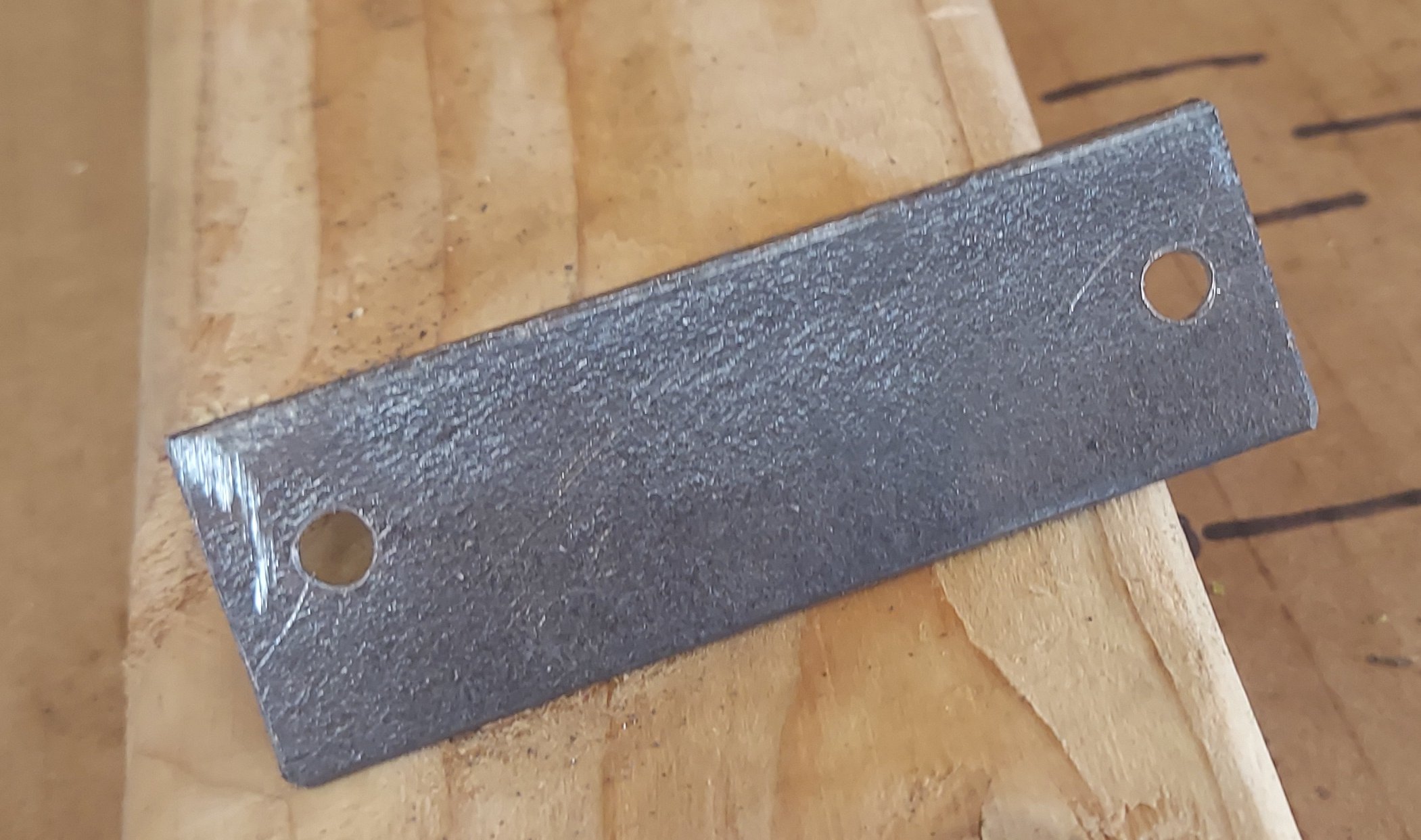
Drill two 7/32 holes in the ends and a 1/2 inch hole in the center. Alignment is not critical
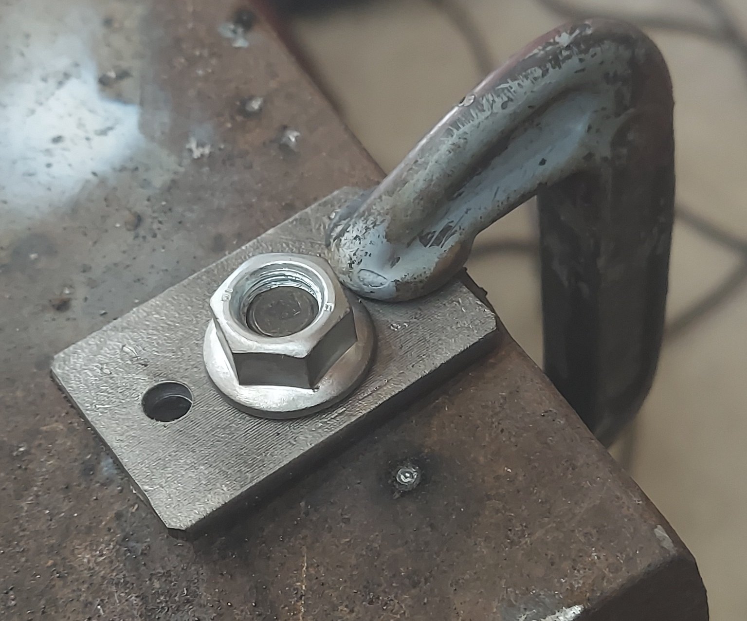
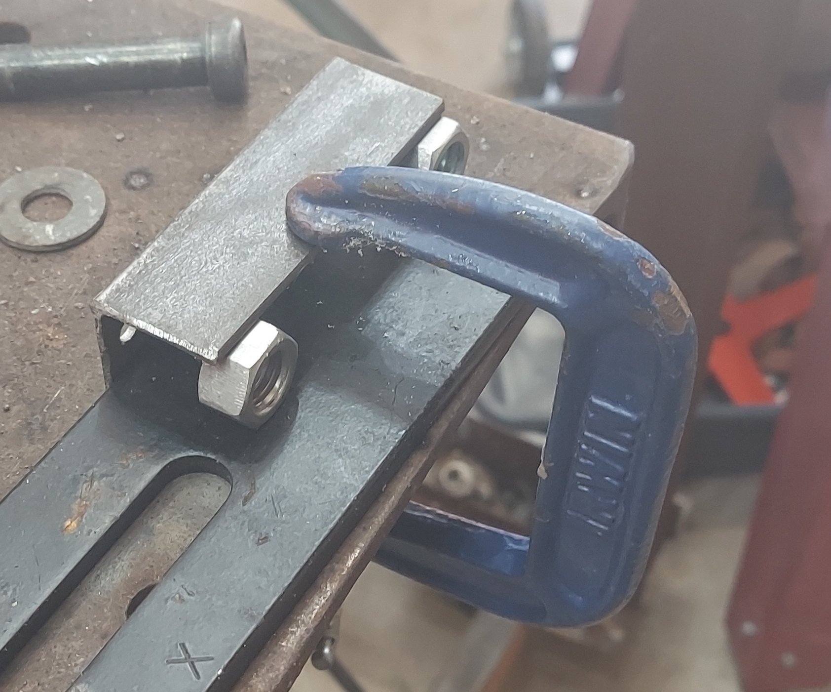
Use a spare M10 bolt and a C-Clamp to hold everything in place
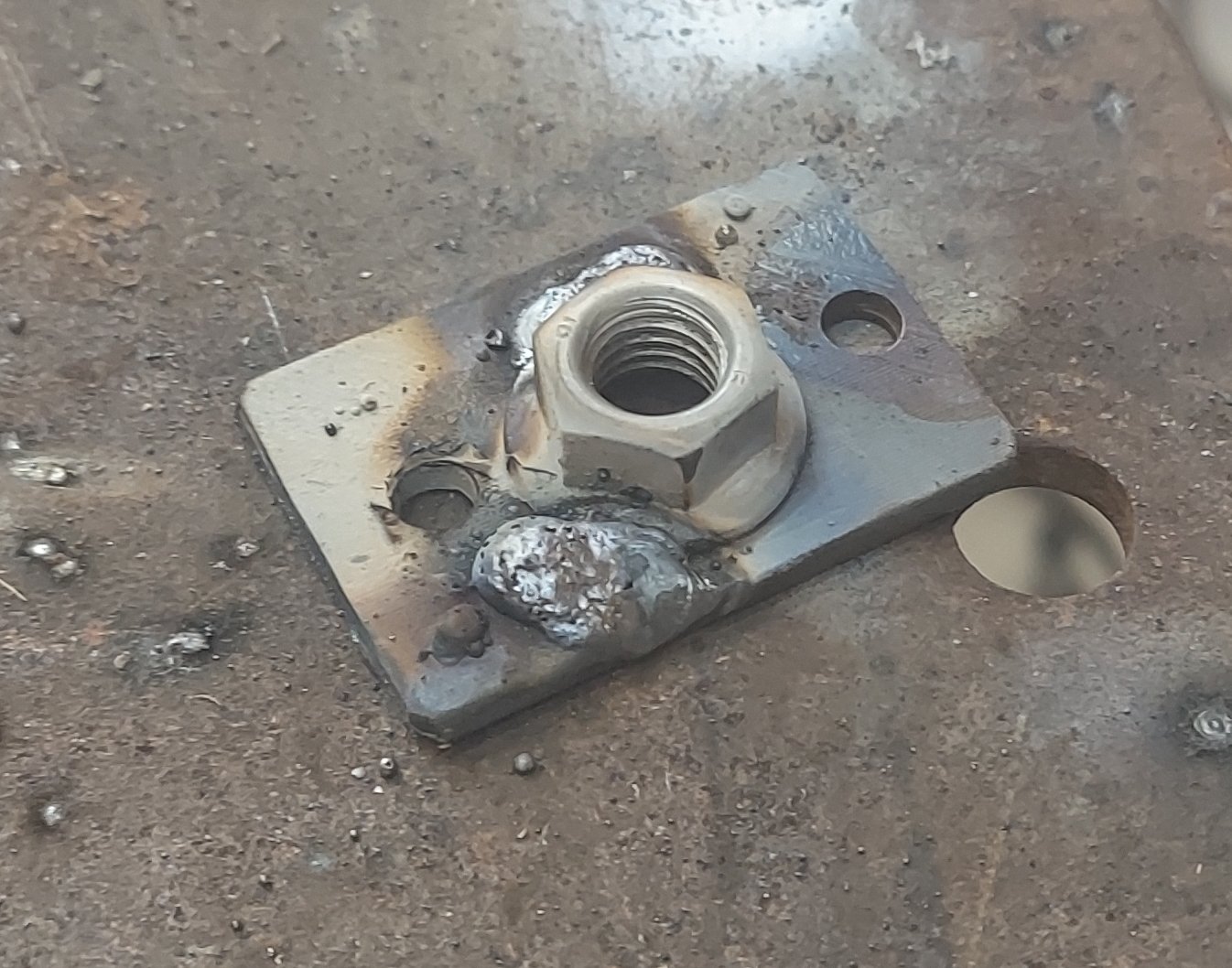
Place two small welds on the edge of the nut flange
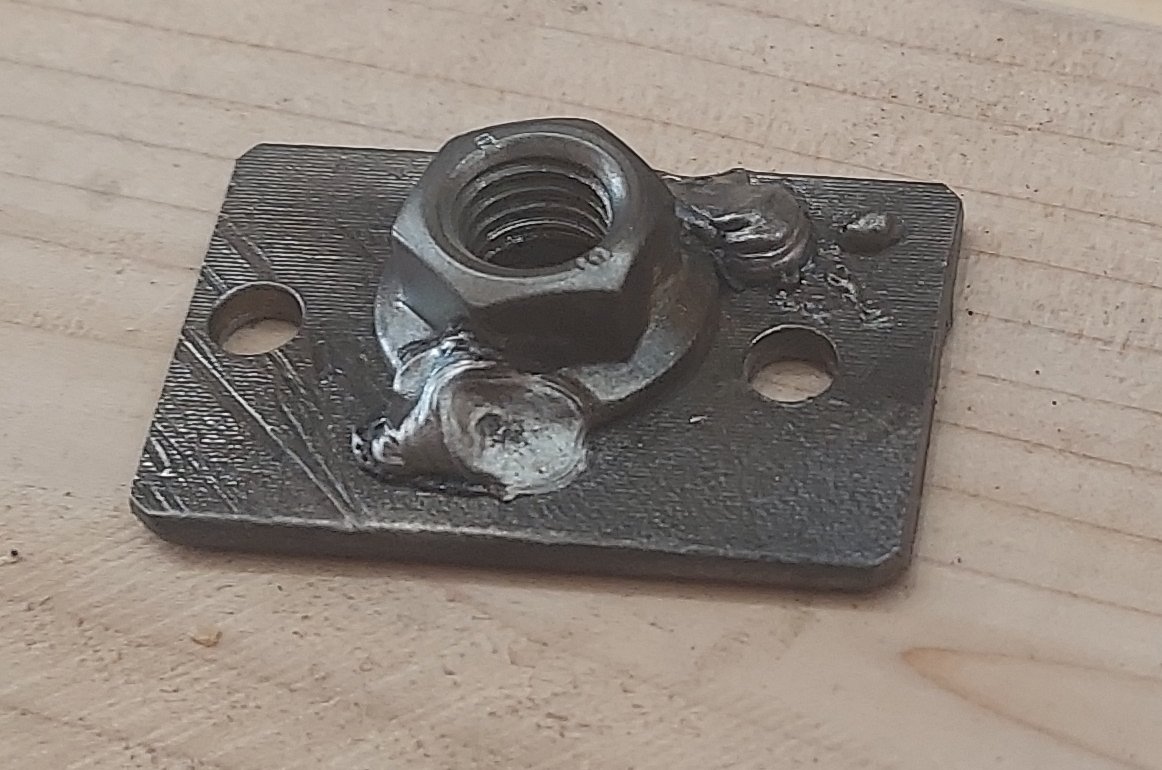
After cleanup the piece is complete
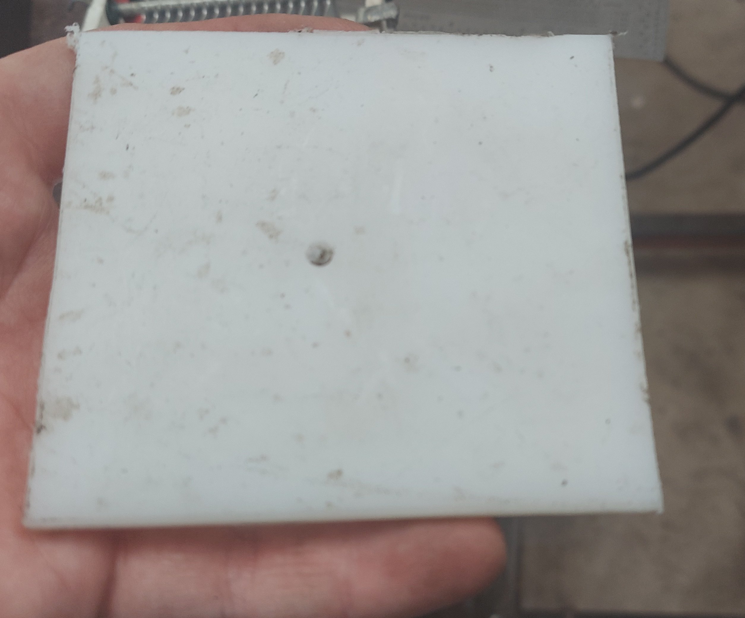
Making the base plate
The base plate is made from a single piece of 1/4 HDPE. Every other component mounts to the base plate. This is designed to be as simple as possible. I cut a 3 inch by 10 inch section using a table saw. You could use a freehand saw if you don't have a table saw.
The next step is to take a razor blade and run it along the hard edges of the HDPE. After cutting with a saw blade these can actually be amazing sharp and pierce or damage skin. The plastic is soft enough the edges can be quickly blunted using the razor blade however.
The base plate requires a huge number of holes. Almost all holes are made by simply laying out the parts on the base plate and marking the appropriate location. I use a scribing tool to create a divot in the plastic which I can see when drilling. You could also use a nail or other marking device.
The holes used for attaching the mounting bracket are large enough to allow 10-24 screws to pass through. These are more than adequate to hold it together.
In the photograph below I attempt to show the major different holes that need to be drilled. Holes for routing wires are added after the fact on as-needed basis.
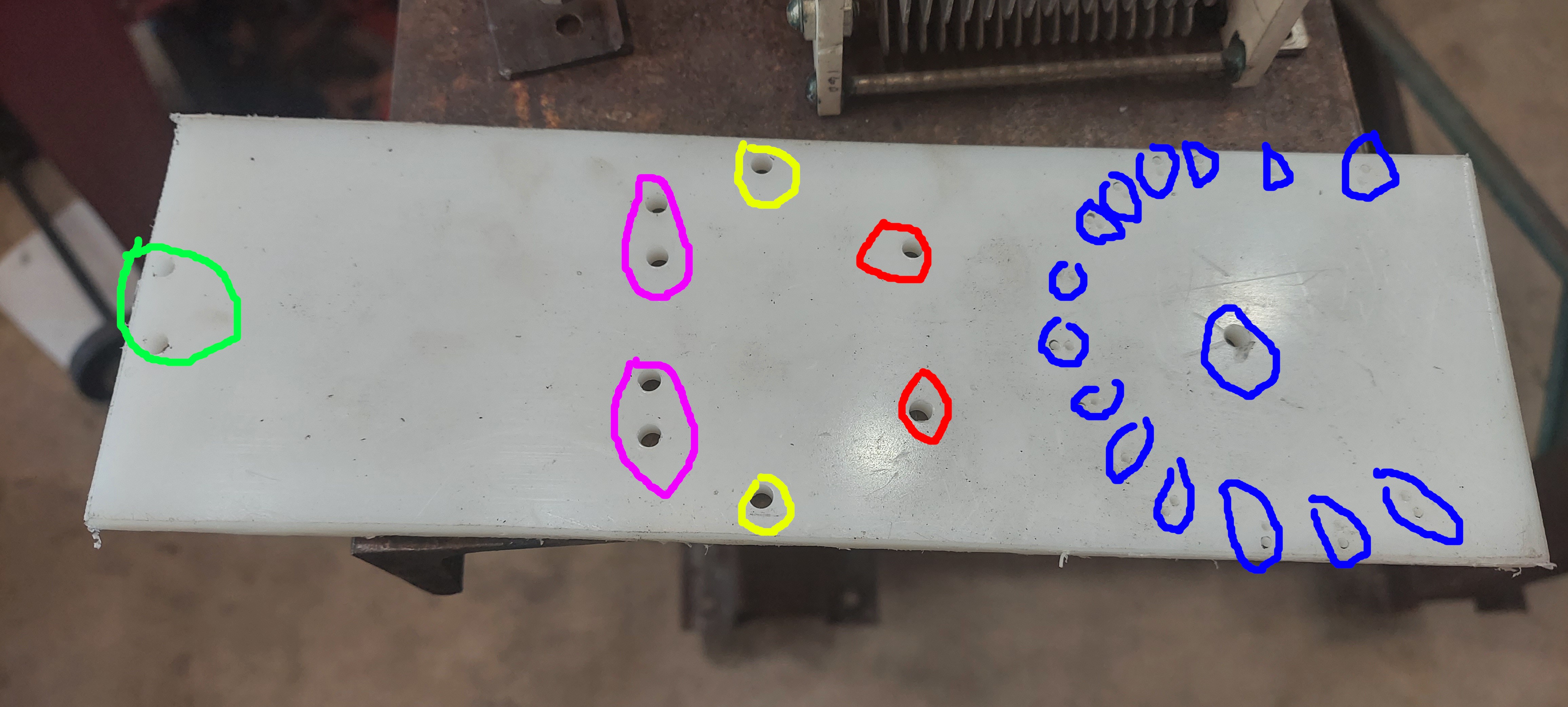
Color Key
- Red: Antenna mounting plate
- Pink: Capacitor zip ties
- Green: Capacitor mounting bad
- Yellow: Mounting bracket
- Blue: Holes for mounting toroid and wire passageways, see this section for an explanation.
Assembling the variable inductor
The variable inductor forms part of an L-Network antenna tuner. Variable inductors are actually one of the easiest components to assemble for amateur radio purposes. High performance designs generally feature complex contact designs or avoid them entirely. For amateur radio a simple coil with many taps is adequate for low power applications.
That being said, the design of a variable inductor still involves tradeoffs amongst the following
- The cost of the materials
- The time spent in assembly
- The ruggedness of the design
- The power loss in the inductor
The method I came up with is as follows
- Start with a toroid, in my case a T200-2 Iron powder toroid from Micrometals
- Wind with short sections of enameled wire, twisting each together as you add them
- Burn the solder away at each twisted together section of enamel wire with a soldering iron. These form the taps
- Drill the base plate at the approximate location of each tap with two 1/16-th inch holes
- Install a short section of bare 1/16th wire in each pair of holes
- Solder the toroid taps to each section of bare wire
If this sounds extremely complex, the photos below should make it simpler to understand. One particular thing is to understand in the winding step that I do not attempt to use a continous section of wire while winding the toroid. Instead, I figured out how much wire I need to make 4 turns around the toroid core then cut many small segments out of that lenghth. Each segment is wound then twisted to the prior segment.
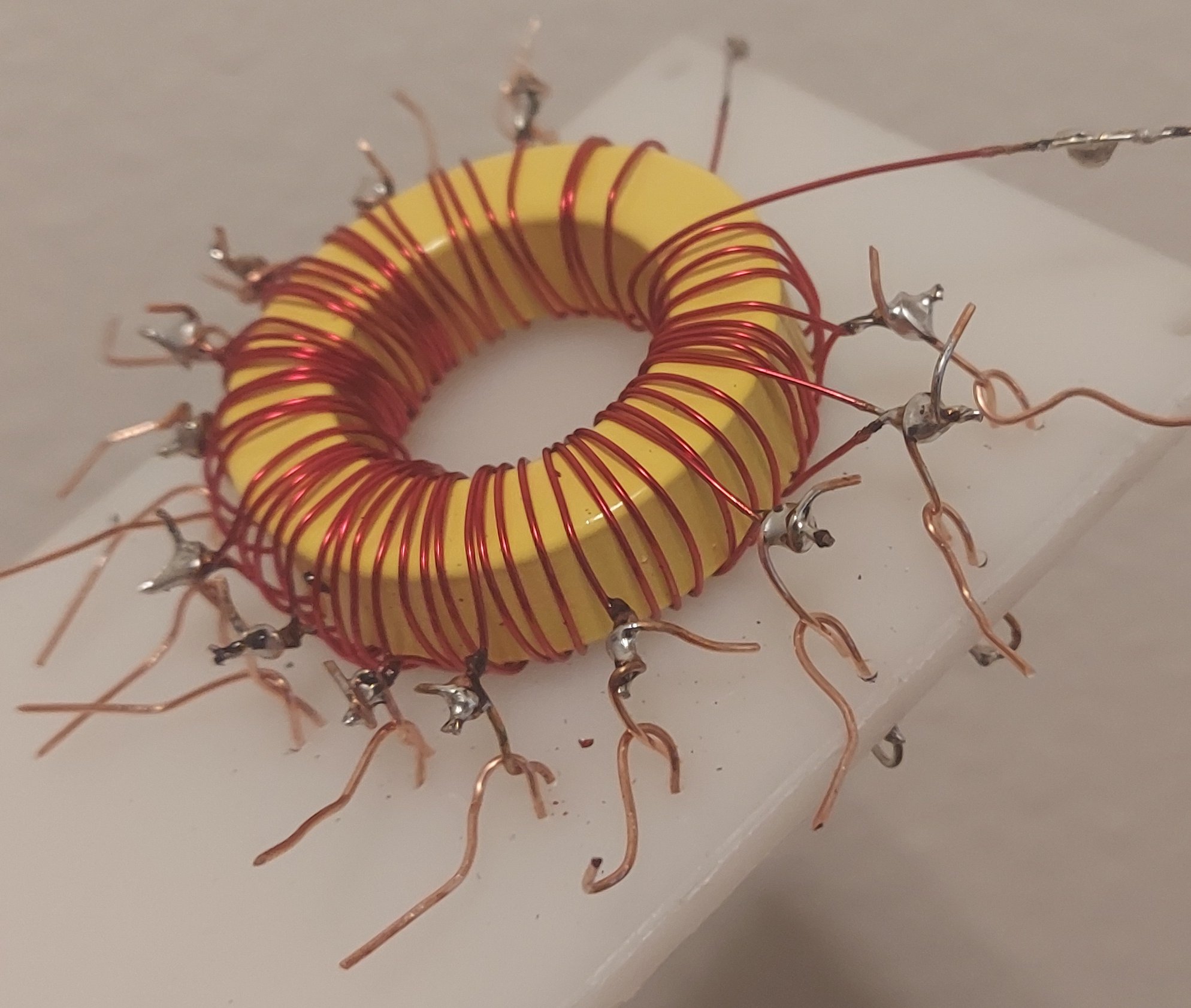
Winding
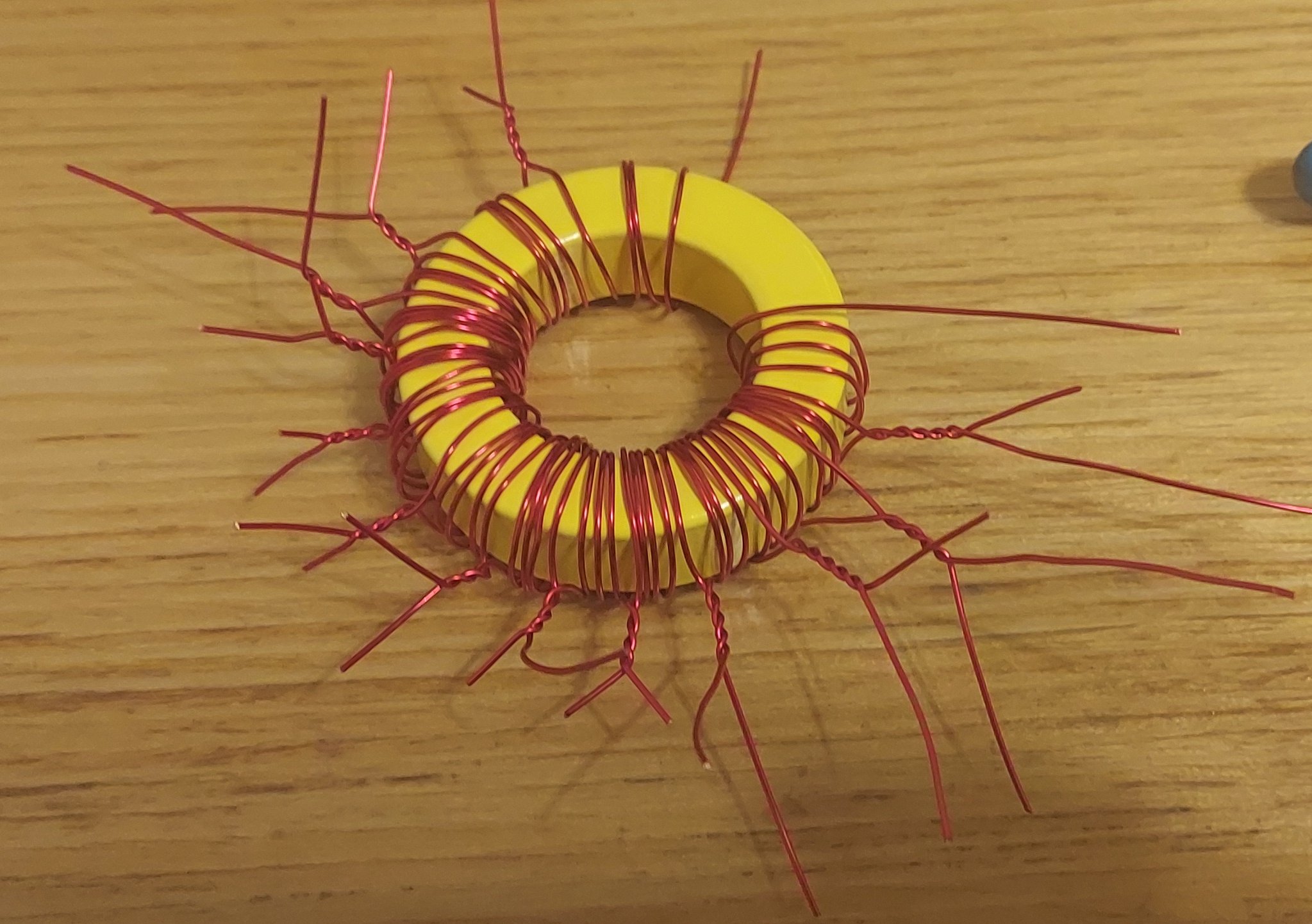
The toroid is wound 4 turns at a time, the twisted sections anchor the wire to the prior turns
The above photo shows the toroid after wire is wound onto the core. After I figured out what length of wire would give me 4 turns around the toroid I cut a whole bunch of segments of that length. I wound the first one on and held it in place by hand. The second segment of wire is then wound onto the toroid core. Then I twist the end of the first section to the start of the second section using a pair of small pliers. this is repeated until the entire toroid is covered with turns of magnet wire.
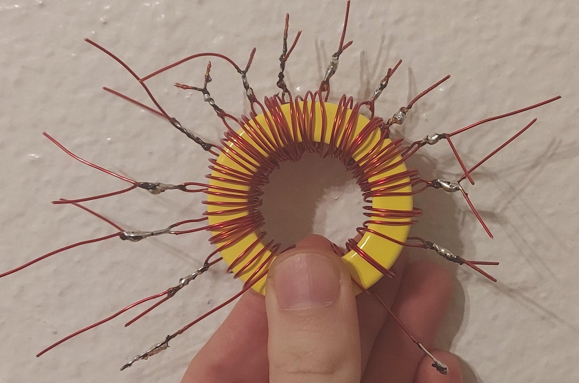
Each section of twisted wire is burnt to bare copper with the soldering iron and tinned
Since enamelled wire is used, twisting the wires together does not connect them electrically. In order to do so you need to burn through the enamel on the wire and solder them. I used by my regular soldering iron to do this, but set it to 900 Fahrenheit. This tends to contaminate the soldering iron tip so I use a brass brush to keep it clean as I go.
After everything is soldered together you can trim off any extra wire.
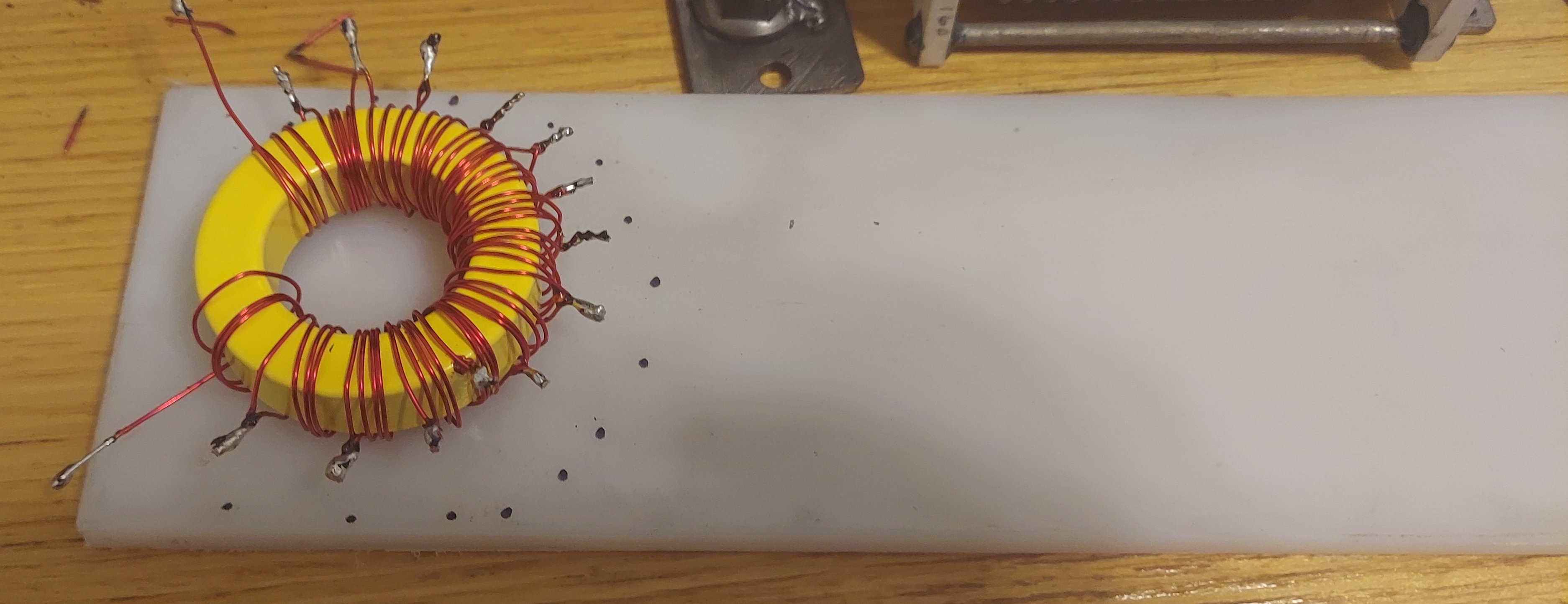
The inductor is laid on the sheet and holes are marked
In order to mount the inductor we need a place to anchor it via each tap. Since the toroid tends to wind up being irregularly wound, I just place the toroid on the sheet of HDPE and use a sharpie to put a dot near each tap. The sharpie does not actually mark the HDPE permanently, the ink just sits on the plastic. So you can wipe any excess clean when you are done drilling
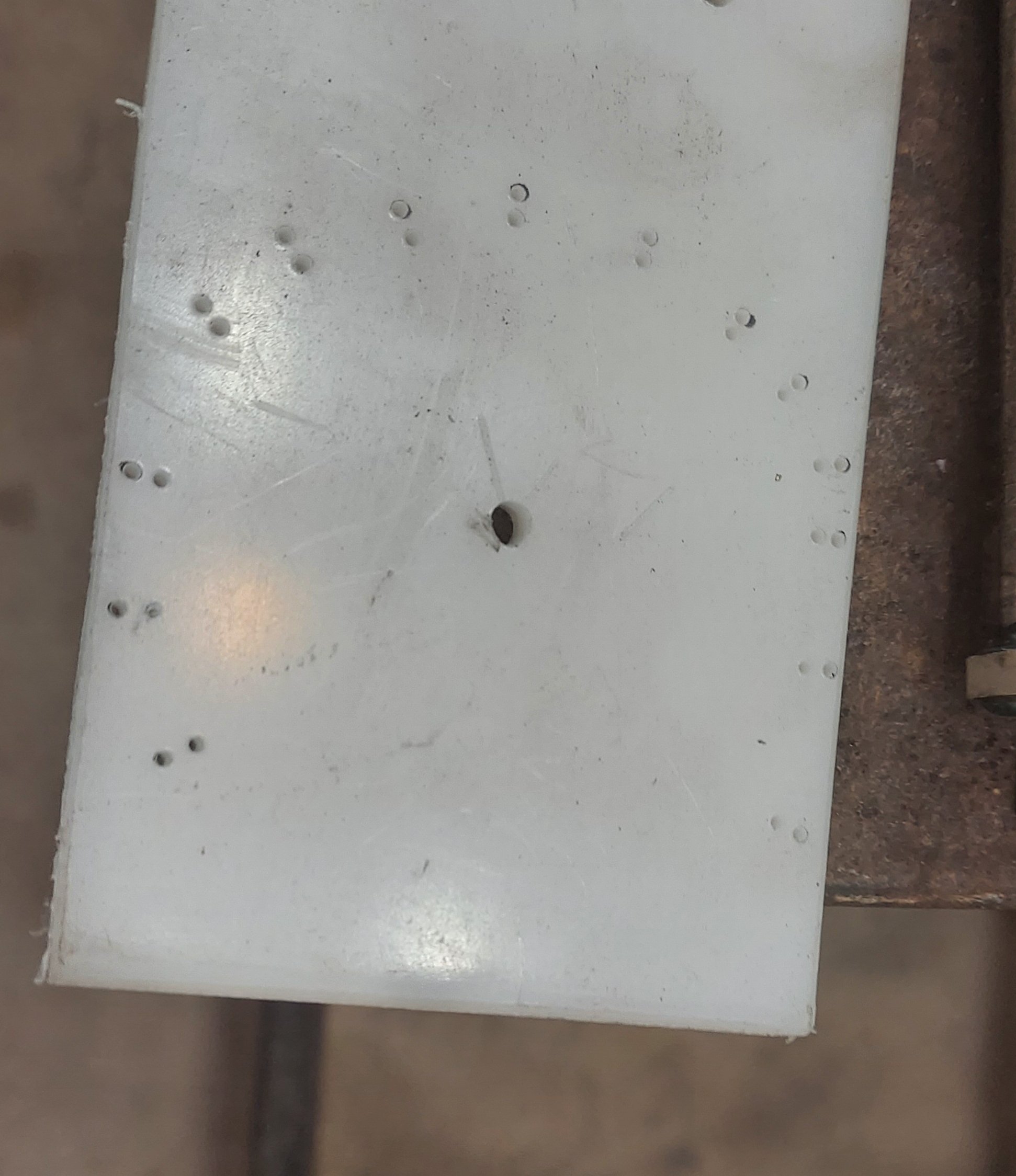
The holes after drilling
At each marked location I drilled a pair of holes using the 1/16th inch drill bit. This is best done with a drill press, but you can use a hand drill if that is all you have.
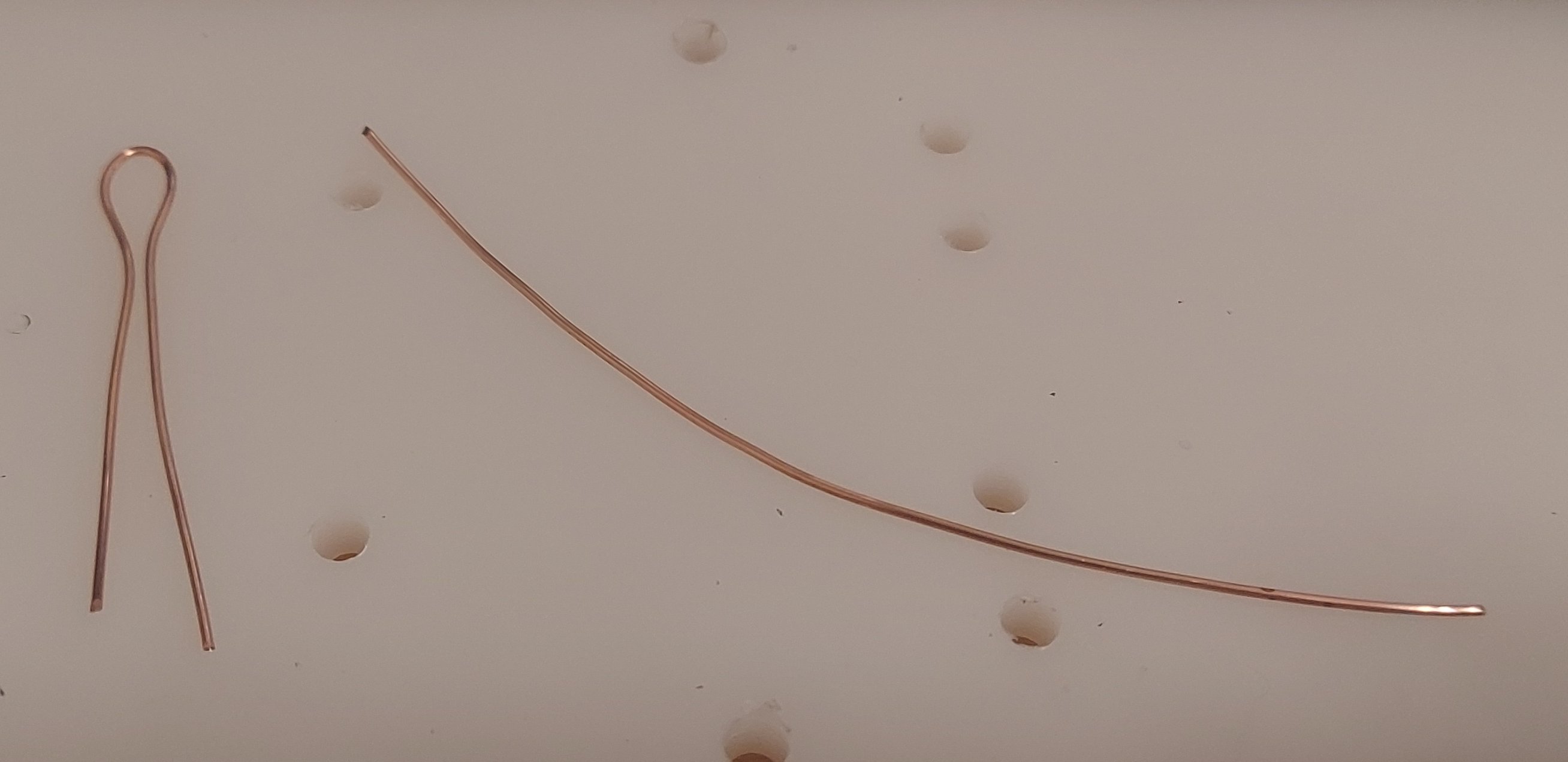
A piece of wire bent and ready to be placed in a pair of holes
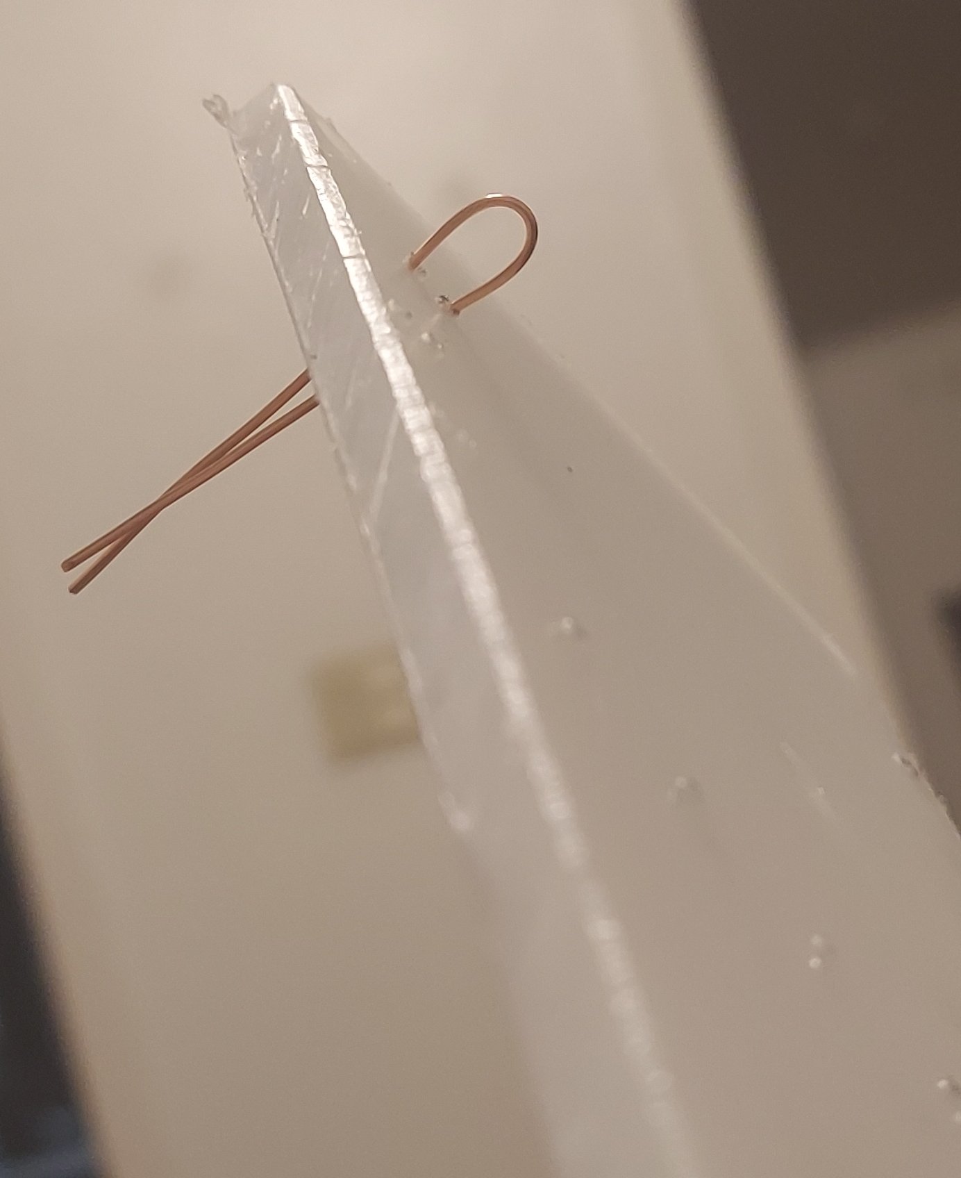
The same piece of wire placed in the HDPE base plate
In order to make an anchor and electrical tap point for each point on the toroid a piece of bare copper wire is bent into a hairpin shape. Then it is inserted into a pair of the holes drilled. This is repeated until all holes are populated.
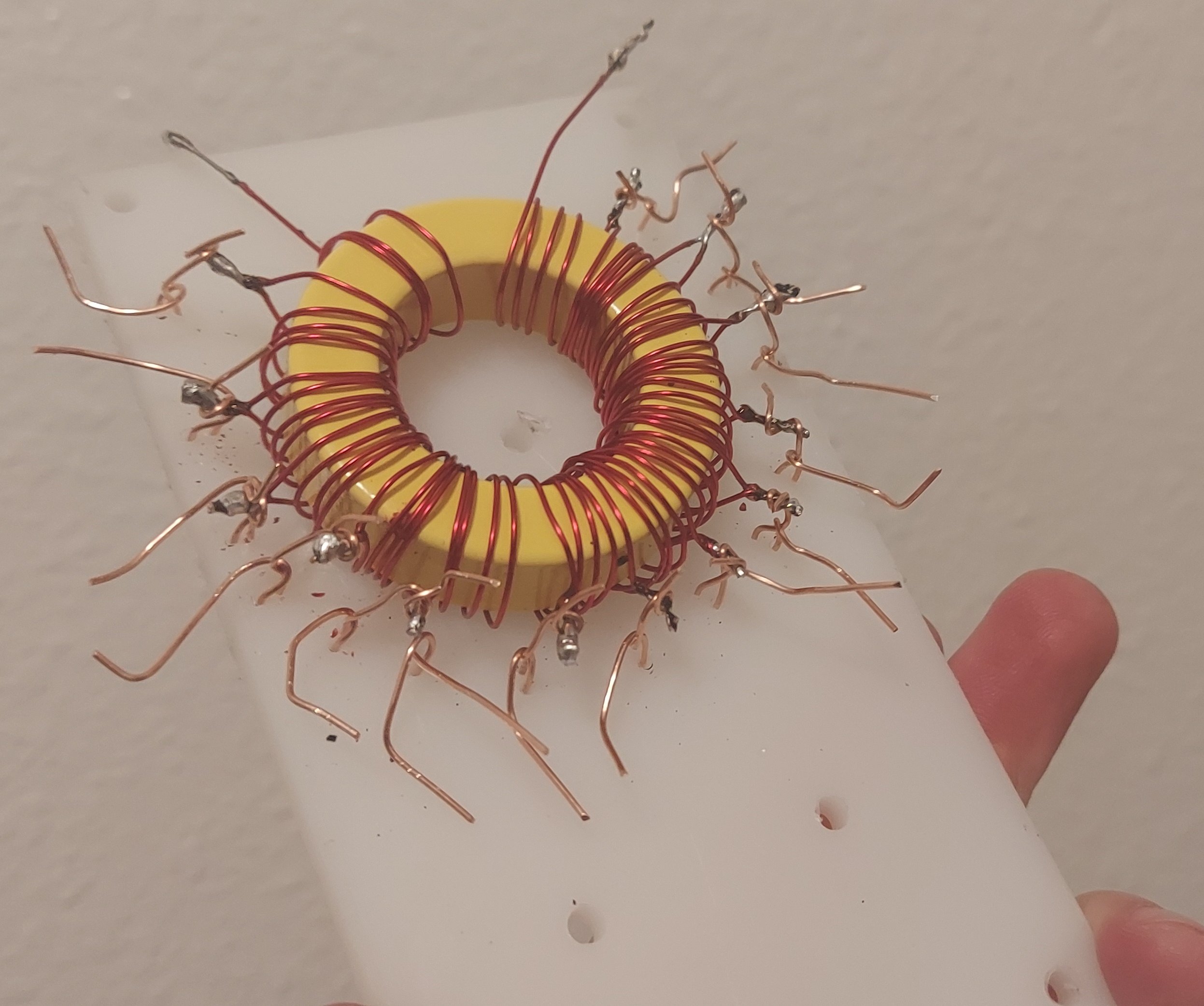
The toroid held in place by the wires
Each wire is soldered to the toroid
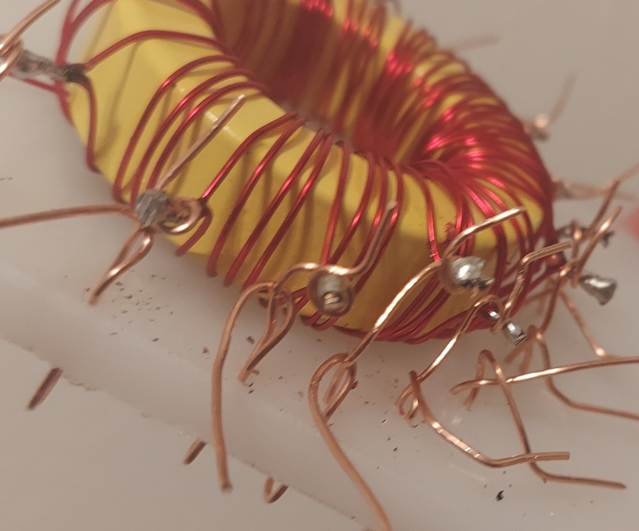
The inductor is placed back on the HDPE in its original orientation. Each pair of wires has one piece of bare copper wire bent back to itself and the other piece of wire is wrapped around one of the taps on the inductor. Then everything is soldered. This alone holds the inductor to the sheet very well.
All wires are trimmed to length
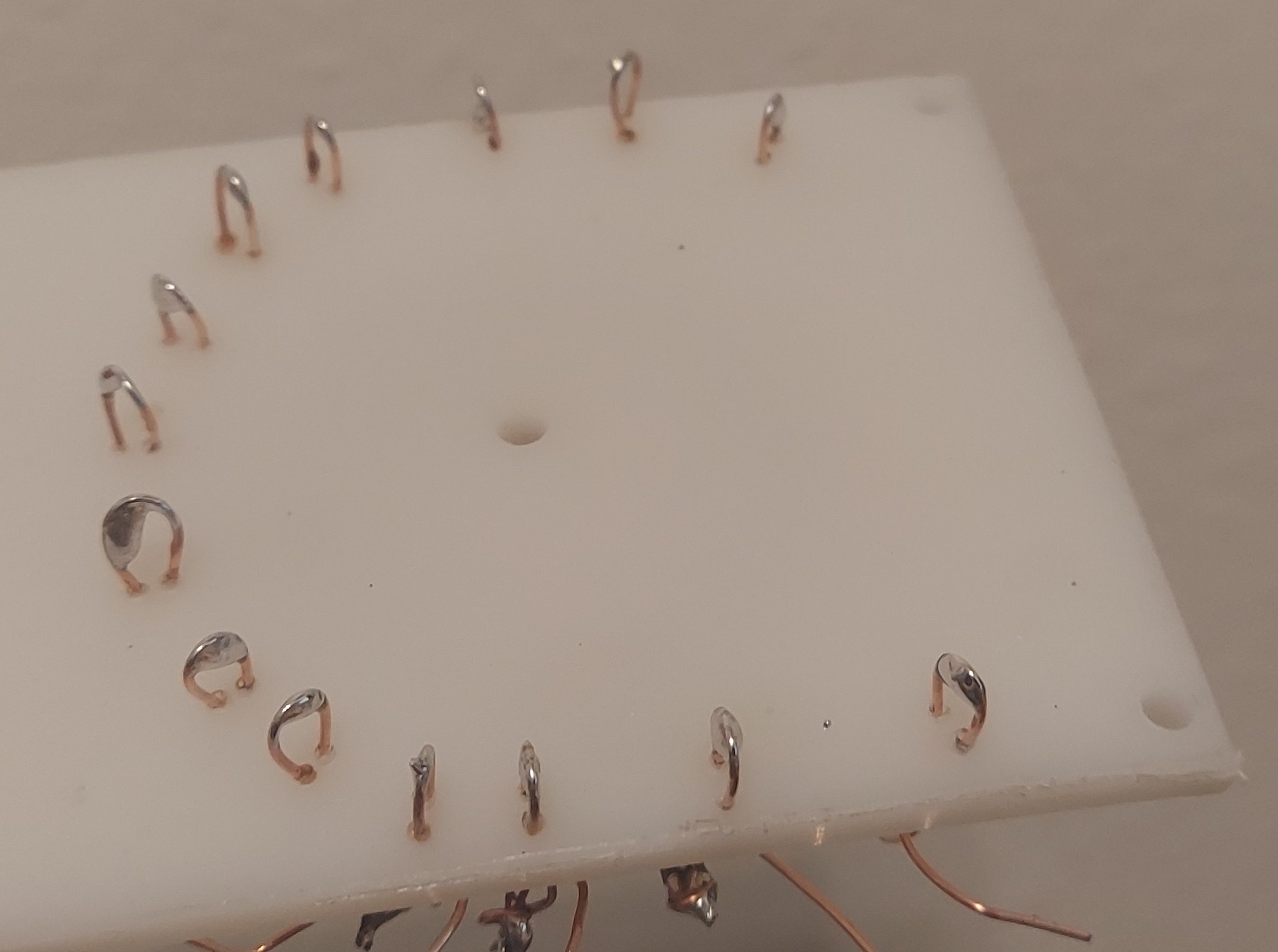
The top of each wire hairpin is tinned with solder to avoid corrosion
At this point the only remaining steps are to trim all the excess wire off. Then the top of each hairpin (now on the opposite side of the board) is tinned with solder. This prevents corrosion that would otherwise occur over time and degrade performance.
The backing plate needs a hole in the center and holes in the corner
The two screws on the end are long 8-32 screws, commonly sold as "furniture screws" at the hardware store.
Mounting
The inductor is mostly held in place by the wires, but I opted to mechnically attach it by creating a backing plate. One hole goes through the center of the inductor and two others are placed on the edges.
The number of turns on the inductor
In my original prototype, I used a mix 43 ferrite toroid for the inductor. This was great because with just 16 turns I had a huge range of inductance. I placed a tap on each turn. The problem arose that as I moved from turn to turn I got the antenna being 50 ohms at 4.1 Mhz. The next turn gave me 3.5 MHz. This meant that the inductor skipped the entire 80m and 75m amateur radio bands! Since the whip is adjustable in length, this allowed me to shorten the whip to hit a target frequency. This is probably the last thing you want to do as making a portable antenna shorter at that low of a frequency just makes the antenna less efficient.
When I set out to build this iteration, I wanted to avoid this problem. I used a type 2 iron powder toroid which does not have as much inductance per turn. I settled on placing a tap every 4 turns. This keeps the number of taps I have to connect to a manageable level. So I wound up with 15 groups of 4 turns. This is a total of 60 turns. If I use the final few turns on the inductor I can tune around in the 80m and 75m band easily.
You might think this is a great. The problem is, the 40m band is only 125 kHz wide for the General class license in the US. So when using less taps, I still wind up "skipping" the 40m band. So now I have to shorten the whip on another band. I've more or less decided carrying a portable 80m band antenna is a fool's errand. So my suggested arrangement for the toroid is 12 taps with 2 turns between each tap. This should give a total of around 24 turns. This only applies if you're using the T200-2 toroid.
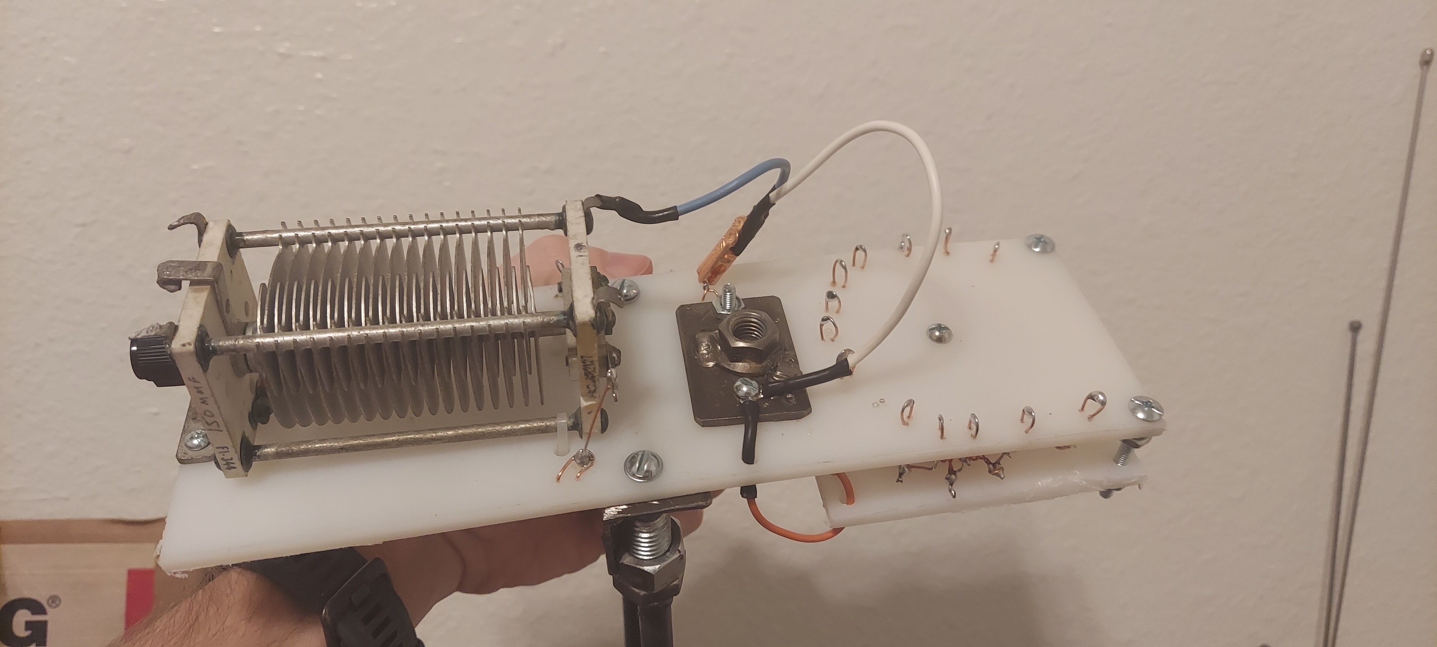
Mounting the variable capacitor
Air variable capacitor generally consist of a series of static insulated plated and rotating insulated plates. When the plates are closest together or "meshed" you get maximum capacitance. Minimum capacitance is obtained by rotating the plates to be as far away as possible. Other elements of the capacitor are usually made by using an insulating material such as ceramic or plastic.
A new air variable capacitor should always have mounting provisions. But they are often expensive new. I sourced some secondhand from eBay for only $11 per capacitor. The downside was one of the ceramic endplates has the mounting tab completely broken off. In the image below you can see circled in green the mounting tab that is intact. I used this was intended with two small 6-32 screws to mount the capacitor. At the other end I improvised and drilled two holes adjacent to the metal bars that hold the capacitor together. Highlighted in pink you can see where I then threaded a zip tie through it all and tightened it down. This is good enough for this type of installation.
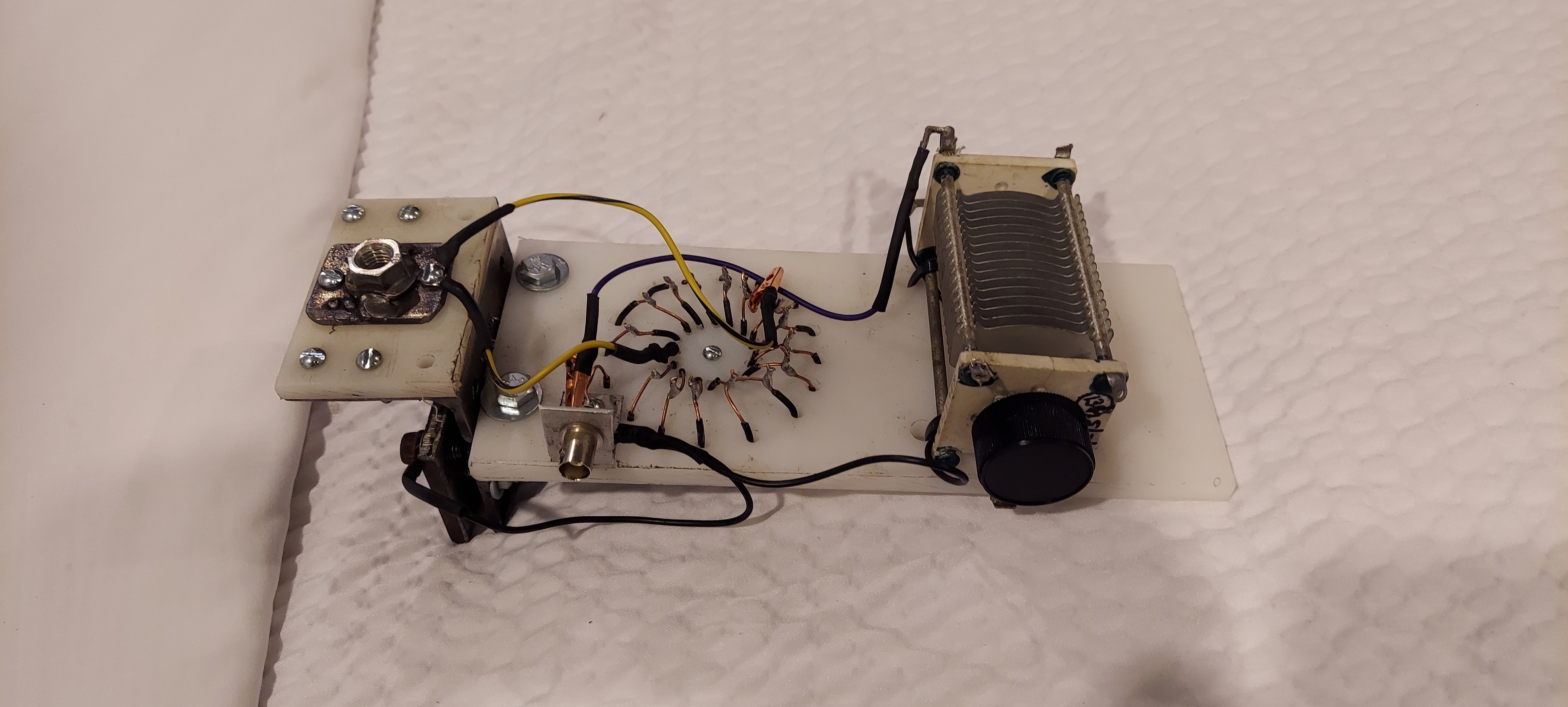
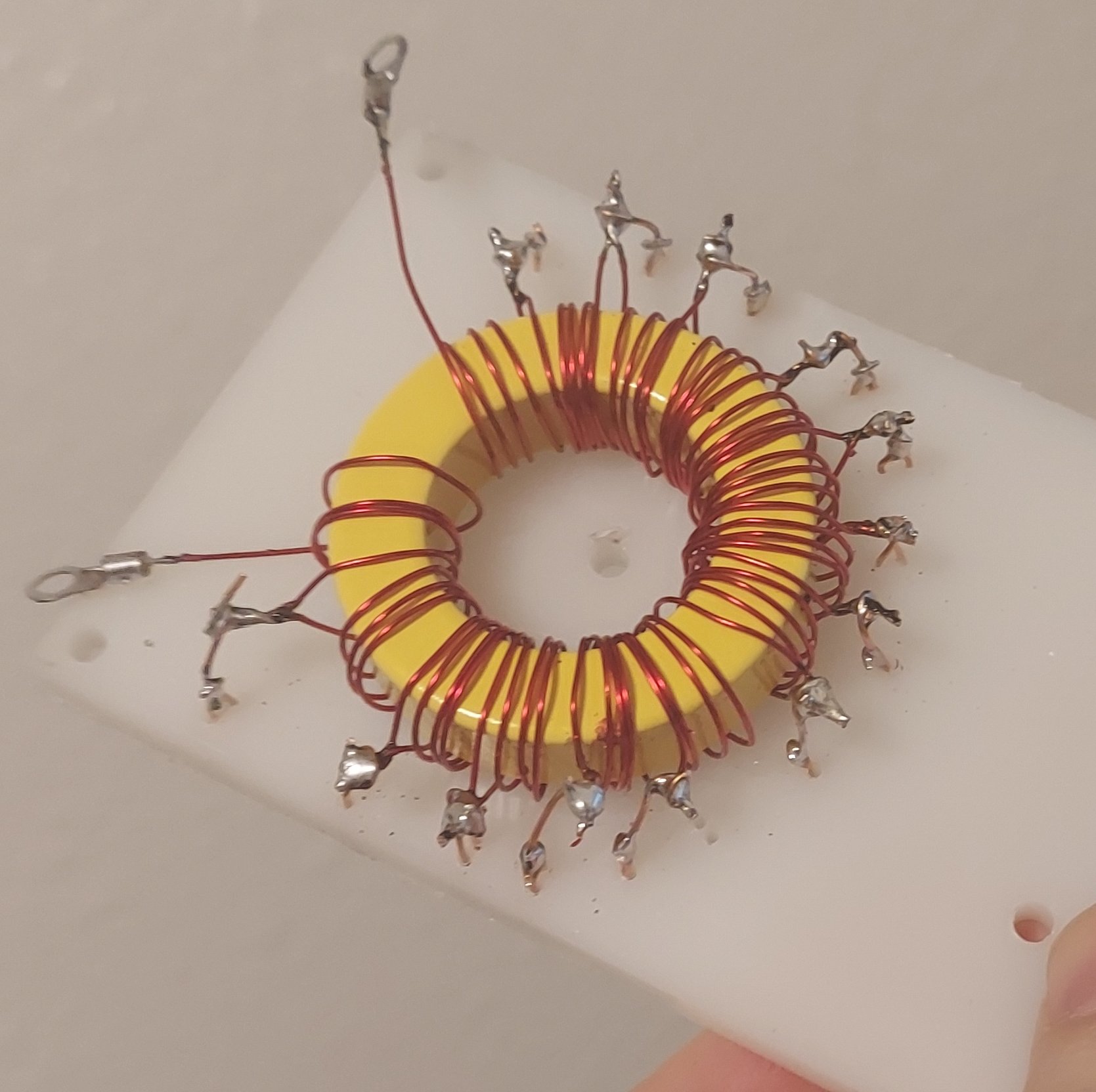
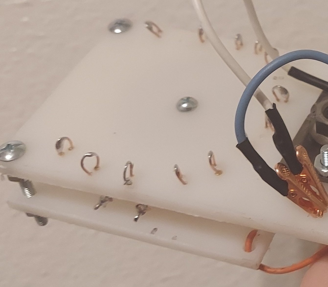
Electrical connections and final assembly
The L-Network is connected together as in the above schematic. There are 3 major items you need to account for
You can see the wires in the assembhled final product
- The inductor tap, white wire with alligator clip. This goes from the antenna mounting plate to the taps OR directly to the feed point to bypass the inductor
- The capcitor tap, blue wire with alligator clip. This connects to the antenna mounting plate or the feed point.
- Ground connections, bare solid copper wire. These not only connect parts of the circuit together but need to be accessible to attach ground radials to.
Additional connections are made using the orange wire, drilling holes where needed to pass it through the plate. The wire I am using is always 600 volt rated stranded wire salvaged from the interals of household appliances.
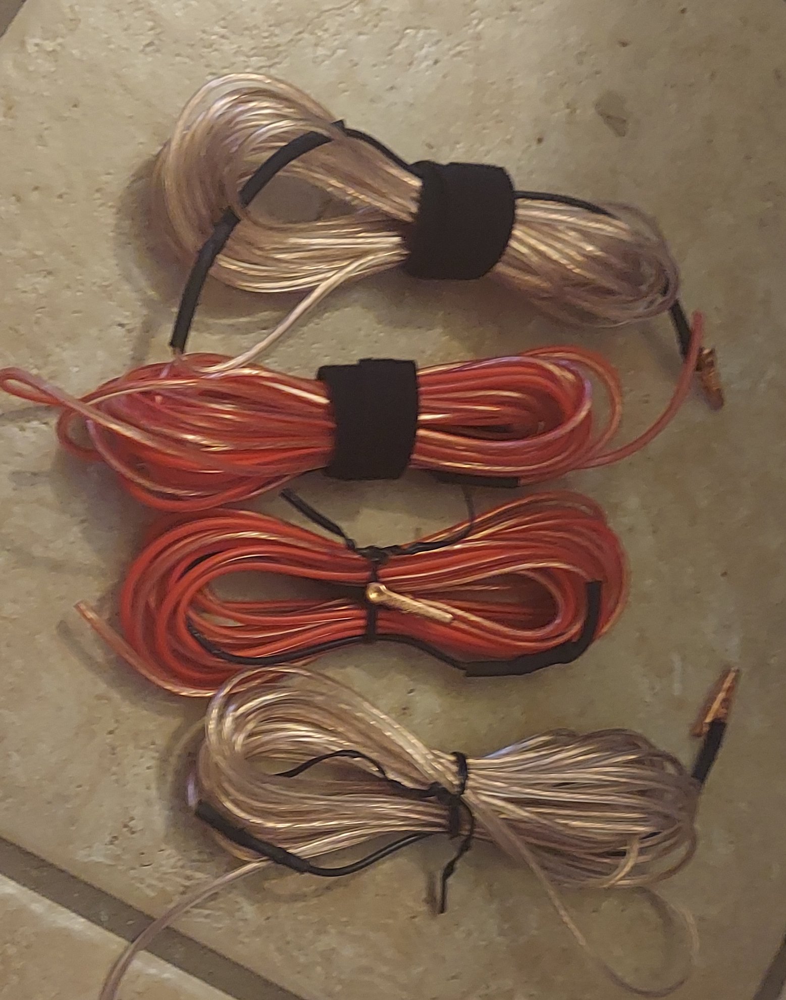
Portable ground plane
Since this antenna is a vertical it requires a large ground plane approximately 1/4 wave in all directions. What I did was took some bifilar speaker wire I had and split it into separate conductors. It is cheap & flexible and I have hundreds of feet of it. I did this twice from 16 ft. sections. So this gives me 4x 16 ft. sections. After that I soldered short sections of scrap wire to the speaker wire and heatshrunk the connection. On the end of that I put a copper plated alligator clips. The advantage to this is if dogs or pedestrian snag the wire the alligator clip just falls off and can be reattached.
This gives me a ground plane I can quickly deploy onto the ground that is adequate down to the 20 meters band. At the lower frequencies it works too. If you want that antenna to be as effecient as possible just make the ground radials longer. At 80 meters each radial should be at least 60 ft in length. This would mean you need to carry around 240 ft in wire total.
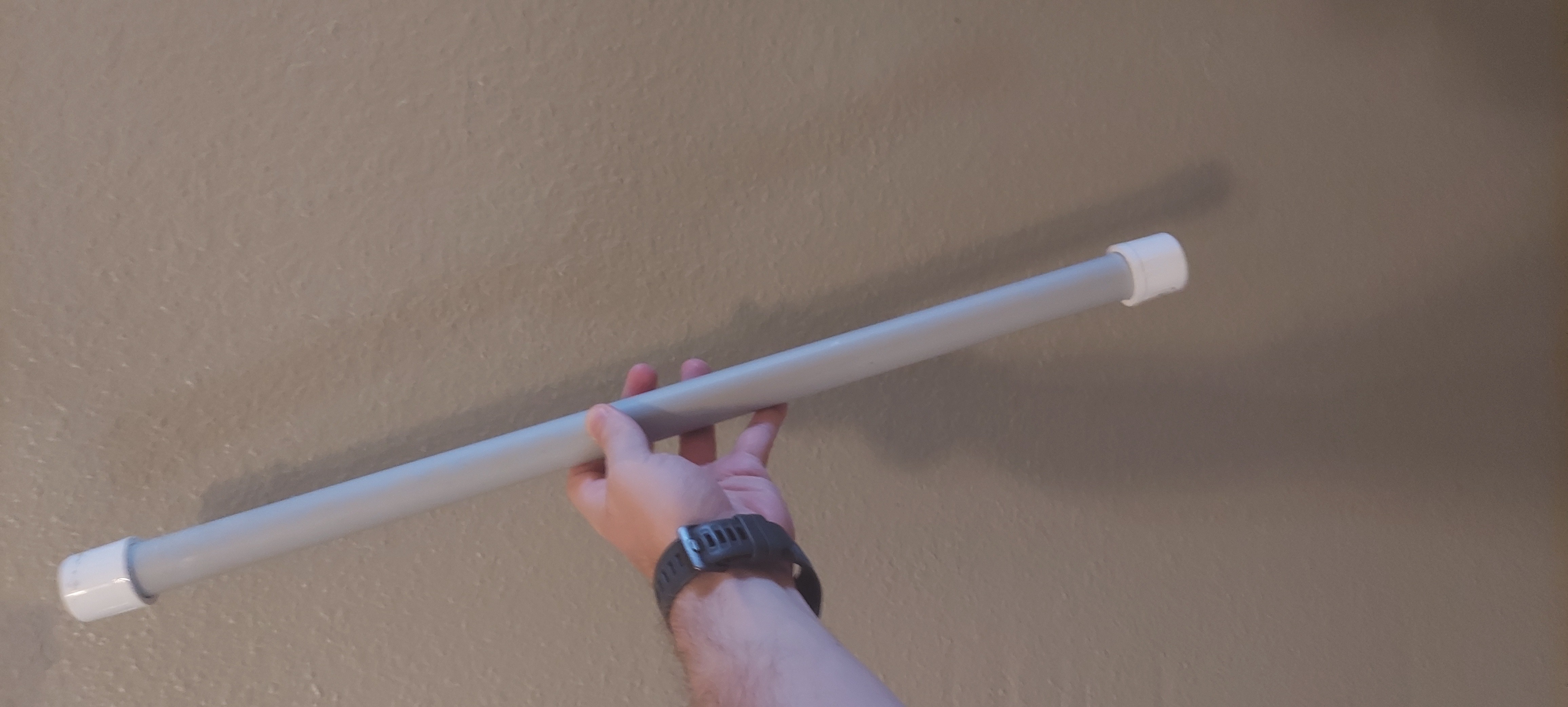
Transporting the whip antenna
Since I intend to carry this equipment in my backpack I need to make sure the whip antenna does not get damaged. What I did was cut a section of 1 inch PVC pipe longer than the whip antenna. On one end I put a PVC cap, so I can place the antenna inside and. A small piece of foam is placed inside as well to cushion the whip. Then the other end is capped off.
Transporting the antenna base and tuner
I need to transport this in my checked luggage when I fly. So my transport option is simple: I take a nice white undershirt and wrap the tuner in it. I put this in the center of my luggage with other clothes. I have never had any damage.
Setup and tuning the antenna
This is my procedure for setting up the antenna
- Install the ground spikes by screwing them into the base
- Push the base into the ground, don't go all the way flush
- Attach ground radials, spreading them out on the ground approximately 90 degrees apart
- Install the antenna, extend the whip fully
At this point the antenna is physically setup but not tuned. I carry around a NanoVNA that allows me to measure the antennas SWR minimum point easily.
20 meters and above
Use the following procedure
- Connect the NanoVNA, adjust to display SWR at the desired frequency
- Short the inductor completely
- Connect the capacitor tap to ground
- Collapse the whip until the NanoVNA indicates minimum SWR at the desired frequency
Operating note: At 20m and 17m this works fine. For higher frequency bands, this doesn't seem to work. I think I've narrowed this down. The antenna impedance always seem to be unusually high for some reason. I have been collapsing the antenna at the base sections. I think this means the sections have poor connectivity to each other when not fully extended. So to shorten the antenna, I think the preferred way is to collapse sections at the top. This means collapsing the antenna down, then not extending the top sections. It is more time consuming, but should work better.
Below 20 meters
Use the following procedure
- Connect the NanoVNA, adjust to display SWR at the desired frequency
- Connect the capacitor tap to the feed point from the transmitter
- Move the inductor tap until minimum SWR is displayed
- Adjust the capacitor until minimum SWR is reached
If the taps on your inductor result in the SWR minimum "skipping" your target frequency then just go to the first tap below the target frequency then shorten the whip to raise the point of minimum SWR.
In the unlikely event the above procedure does not result in a usable SWR, swap from configuration B to configuration A as shown in the schematics above. This is rare, but can happen.
Testing
The previous prototype had made many SSB contacts on multiple bands using only 6 watts of output power from my Yaesu FT-818. So I was excited to use this improved version to say the least.
The first tests were done while I was operating portable in California. I was using my Yaesu FT-100 on battery power, running around 20 watts of power. Unfortunately the prior week we had a large solar flare hit the Earth's ionosphere. Propagation was almost non-existent most of the times I managed to operate. I was able to make several contacts on the 20 meter band however.
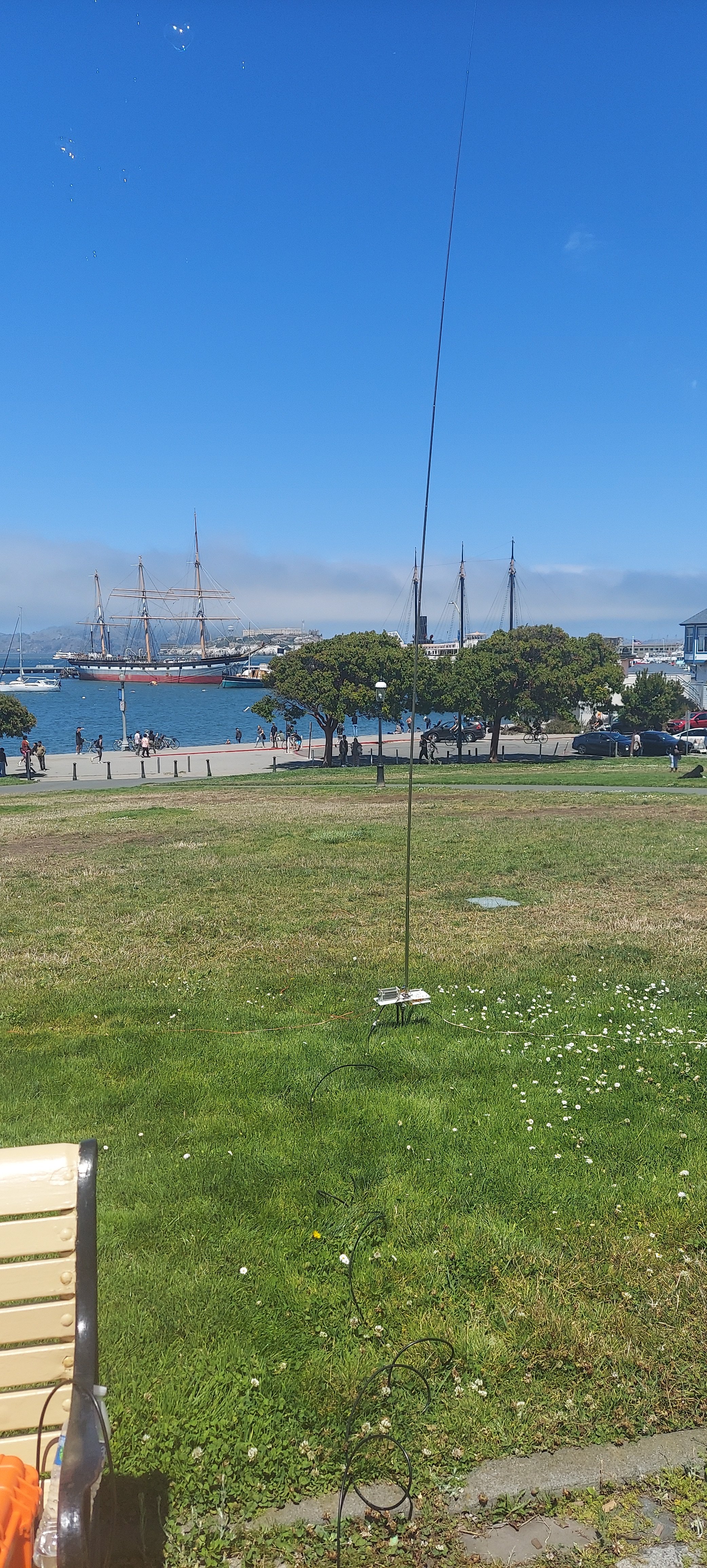
More importantly I was able to carry this around in my backpack while I was walking around in California and operate from wherever I wanted to. In the next week I would make several contacts getting good signal reports from multiple stations in the continental United States.
If you can run CW or digital modes while portable, I suspect you will find this antenna excellent!