Converting a drill press into a milling machine
I found this drill press on the side of the road. I have always wanted to try converting a drill press into a mill. But I never could justify modifying my existing drill press. So I decided why not try it?
You are probably reading this because you are intersted in this sort of thing. I am presenting here the steps I ended up taking that worked. There was lots of learning I had to along the way. It's way too much to present. I also don't recommend doing this unless you can get the materials for free and have lots of spare time. If you actually need a small mill then Little Machine Shop is a good place to begin your search.
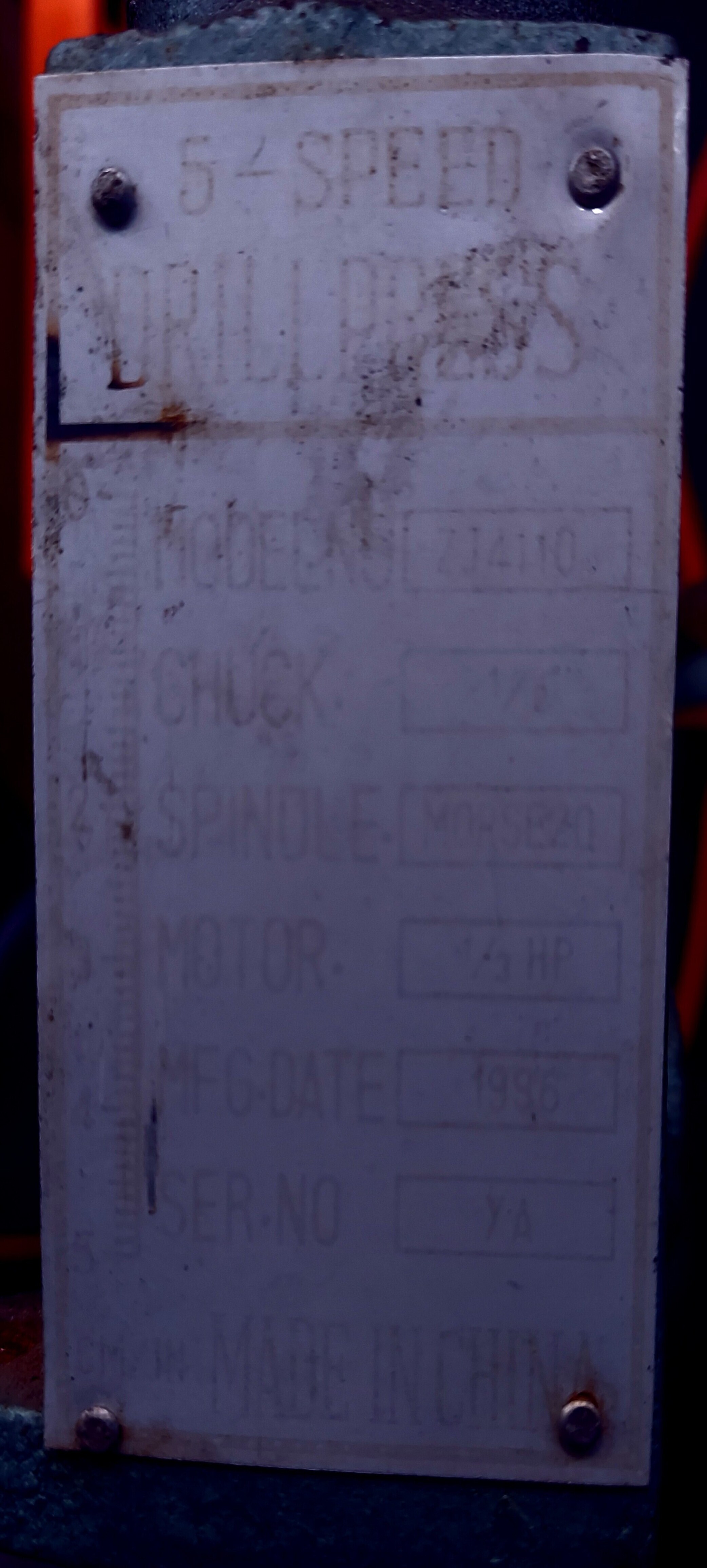
Enhanced image of the data plate
This is the original nameplate from this which is heavily faded. I enhanced the image to make it readable
- Model ZJ4110
- Chuck 1/2
- Spindle MORSE20
- Motor 1/5 HP
- Manufacturing Date 1996
- Serial Number YA
Since I found this in 2023, this drill press is over 20 years old. It looked like it had been stored outdoors. It actually ran when I found it, but barely. I think this was a cheap "tool truck sale" drill press. If you look closely, there are a number of things that indicate how hilariously bad this thing is. The scale on the front left of the label says "CM/in" but there is no scale in inches. The taper is listed as "MORSE20" but there is no such thing and this drill press does not use a morse taper at all.
Disassembly
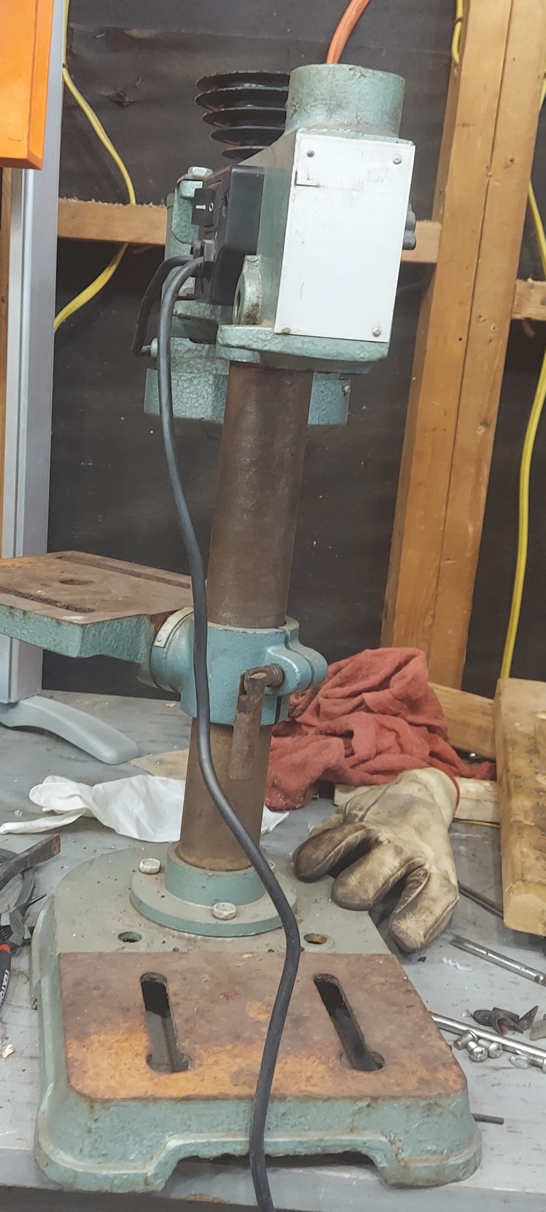
I don't seem to have any photos of this before I started taking it apart. Here it is in some state of disassembly.
Steps
I'll quickly summarize how I took this apart. You can find a complete video of someone taking apart this drill press here.
- Flip up the top cover to access the belt
- Remove the belt
- Remove the set screw holding the motor pulley on
- Remove the set screw holding the spindle pulley on
- Remove the four bolts holding down the top cover
- Remove the top cover
- Remove the set screw holding the motor adjustment in place
- Remove the 2 bolts holding on the motor bracket
- Remove the two 17mm nuts holding on the left side of the hand feed shaft
- Remove the clockspring on the left side of the hand feed shaft
- Remove the hand feed out the right side of the drill press
- Remove the depth stop from the quill
- Remove the set screw on the front right side of the drill press
- Remove the quill from the drill press by lowering it down out of the bottom
- Remove the snap ring holding the spindle top bearings in
- Remove the shaft coupler on the top of the spindle
- Pull both bearings out the top of the drill press
- Remove the snap ring off the quill shaft
- Push the quill shaft out the opposite end of the quill
- Pull the bearings out of the top and bottom of the quill
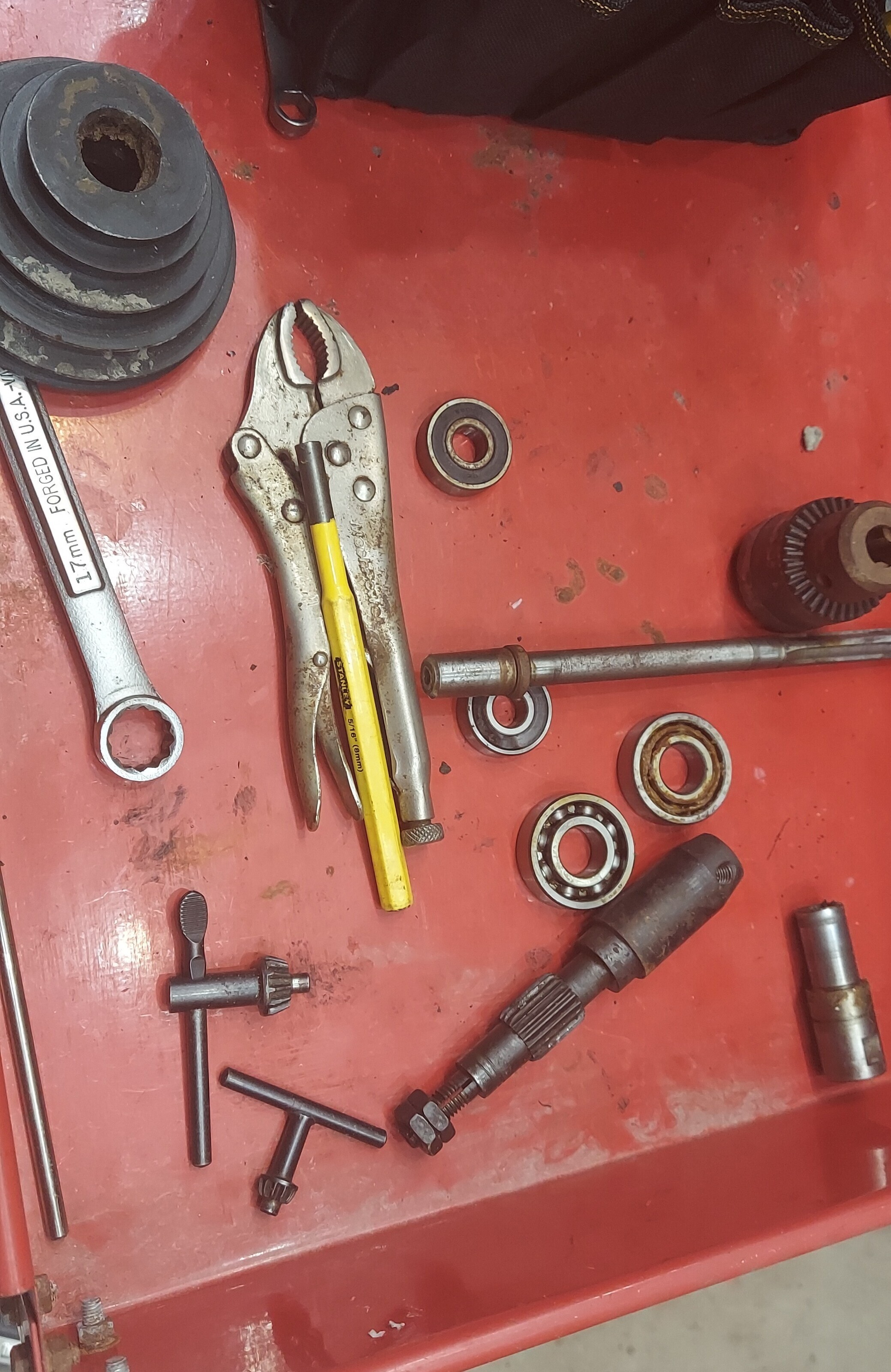
You wind up with a bunch of parts like this when you have it taken apart
Repair
This drill press needed some repair before I could really do anything with it.
replacing the bearings
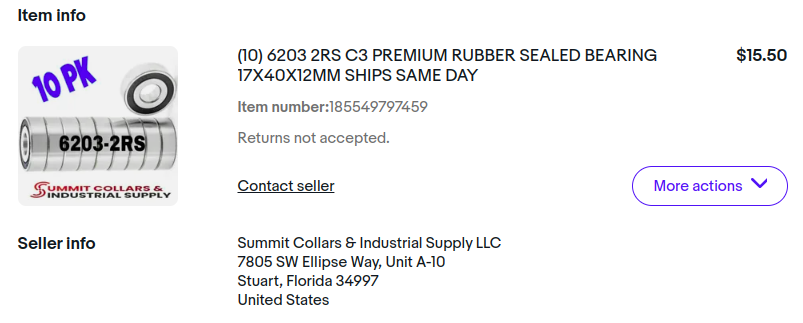
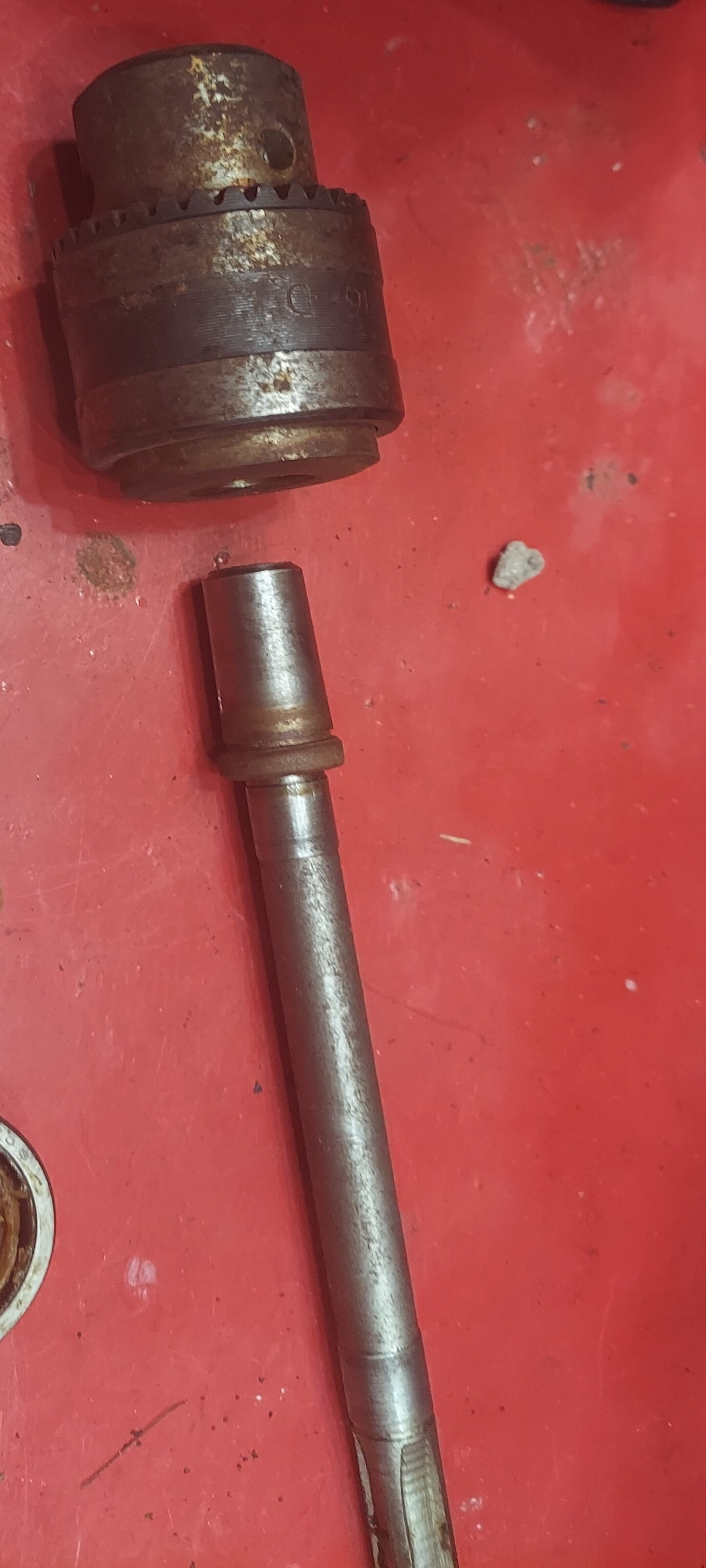
This drill press has only 4 bearings total that are easily accesible. The two that hold the spindle pulley in place are 6203 bearings. It appears they stacked up two 6203 bearings since they only bearings on one end of the shaft. The original bearings are an open design, but I replaced with part number "6203RS" which is a shielded bearing.
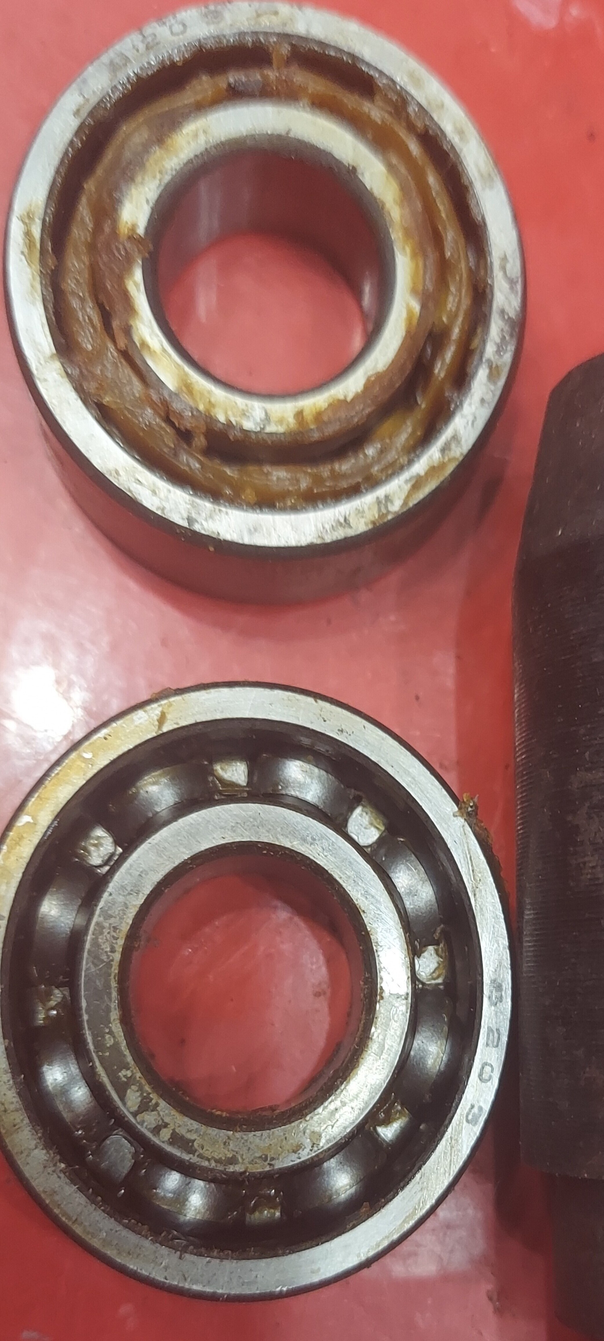
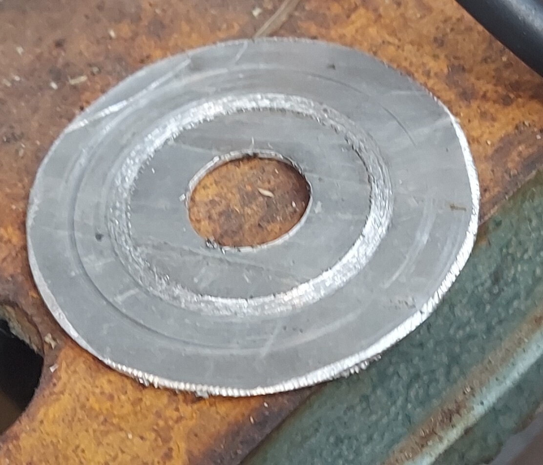
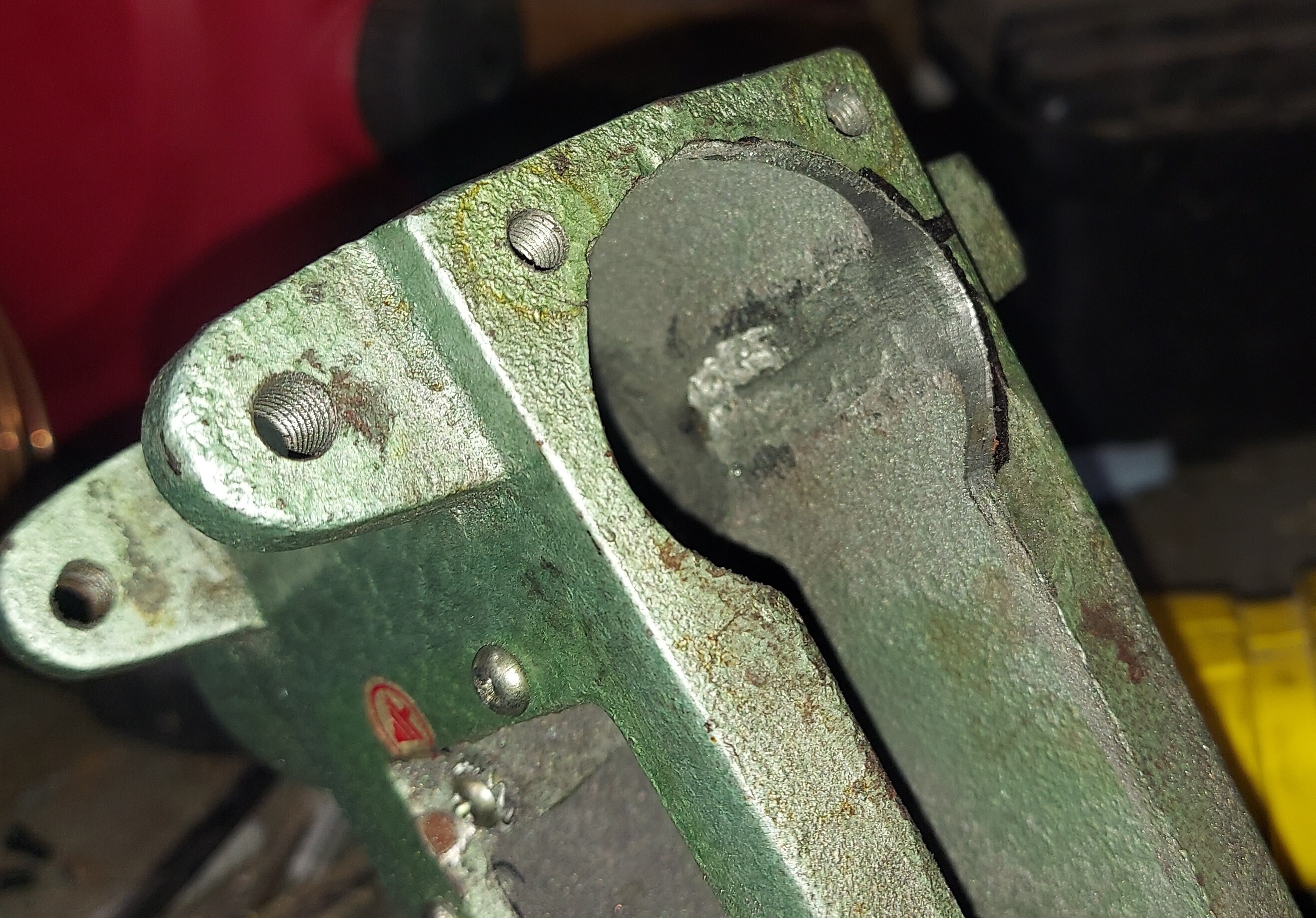
The original bearings are an open design
The spindle bearings, held in with an internal snap ring
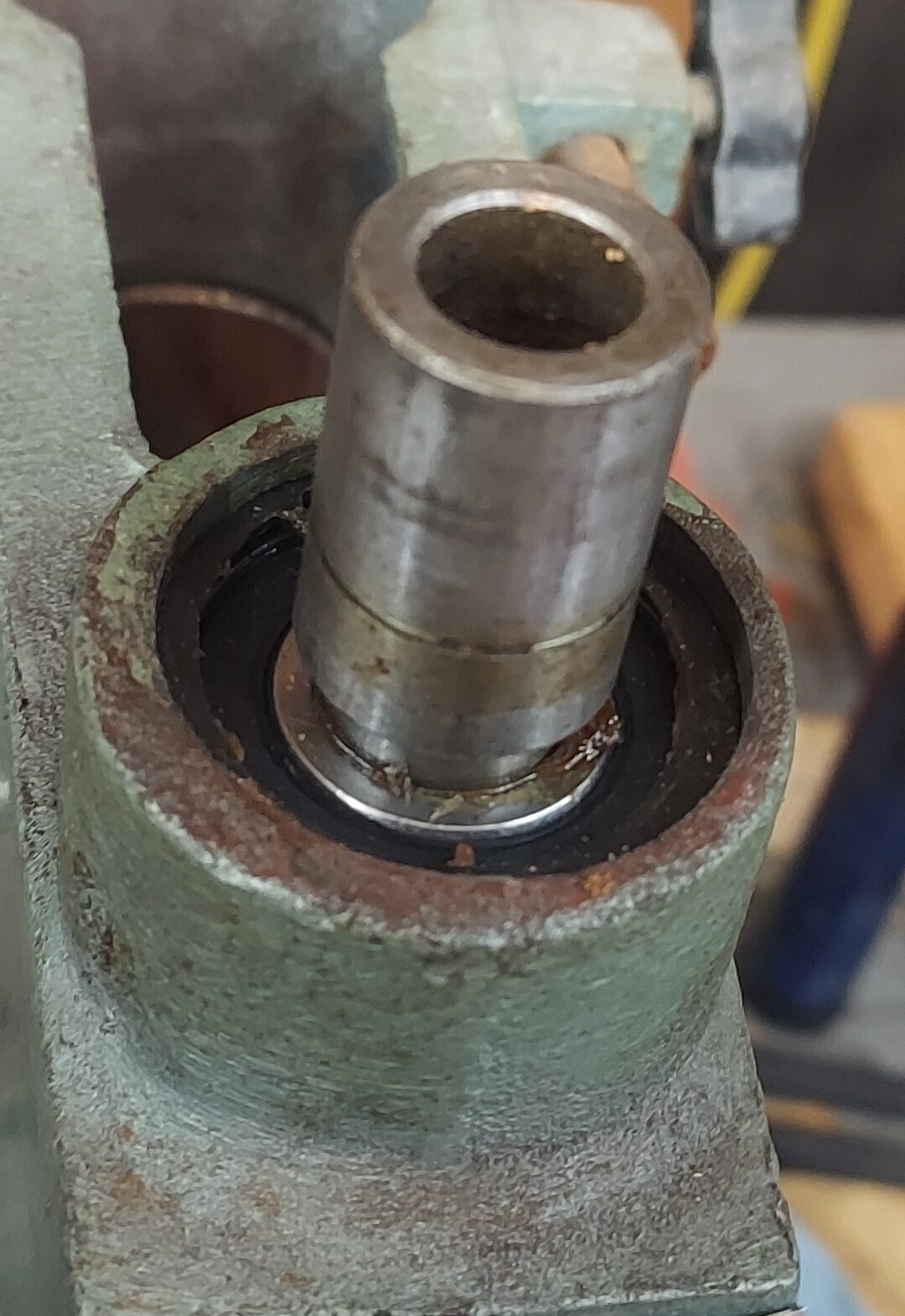
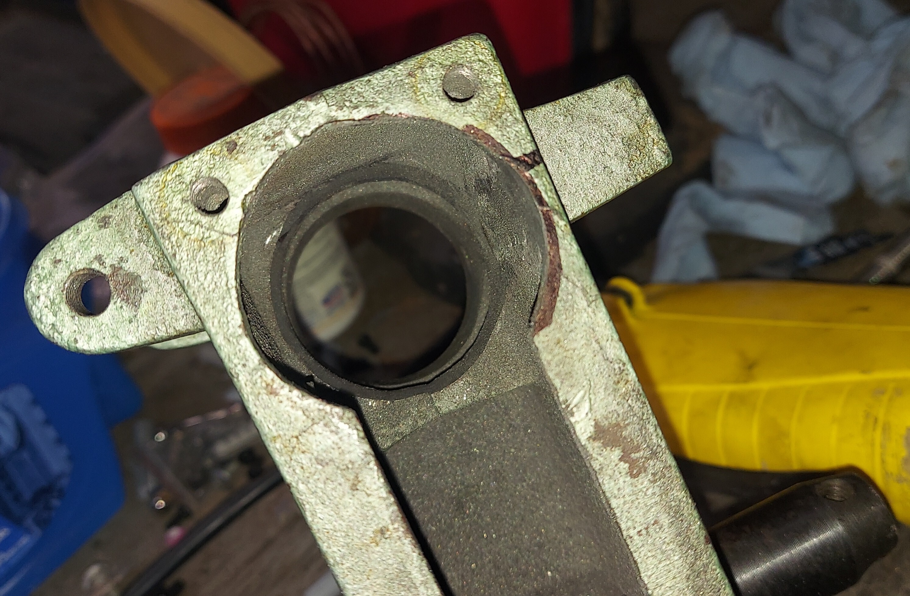
The quill uses two 6201 bearings. One at the top and one at the bottom
The quill top bearing
These bearings allow the shaft to rotate, which has the drill chuck on the opposite end. The top section of the shaft is squared off and rides in the top of the spindle pulley adapter. This is how the quill can move up and down while still carrying rotation. The top bearing I replaced with another 6201 bearing. The bottom bearing I wanted to put in a bearing that could carry load in all directions. After doing research I determined a tapered roller bearing was appropriate. This is basically a wheel bearing like you'd use in a car. Except in this case very small. The equivalent part number is "30201". The only source I found in the US for this had them starting at $18 each. After some searching I found them on AliExpress for basically nothing.

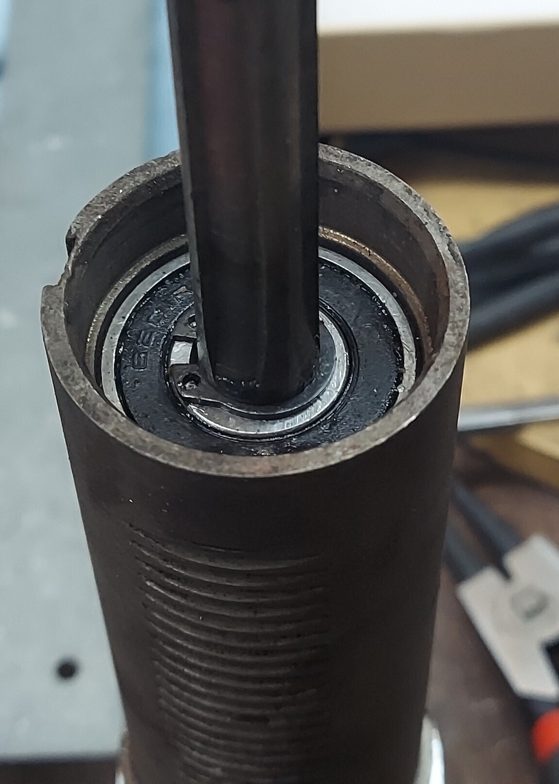
Once I had the tapered roller bearing I had to come up with a way to install it. Traditional ball bearings like the 6201 are assembled into a single piece that you just press in. Tapered roller bearings are typically supplied as a bearing race and a bearing "inner" section that sits in the race. The race was simply driven into the bottom of the quill since it has the same outer dimension as the original 6201 bearing. I made an aluminum shield that cover the bottom of the bearing. I packed the rollers full of wheel bearing grease, since they come without any grease.
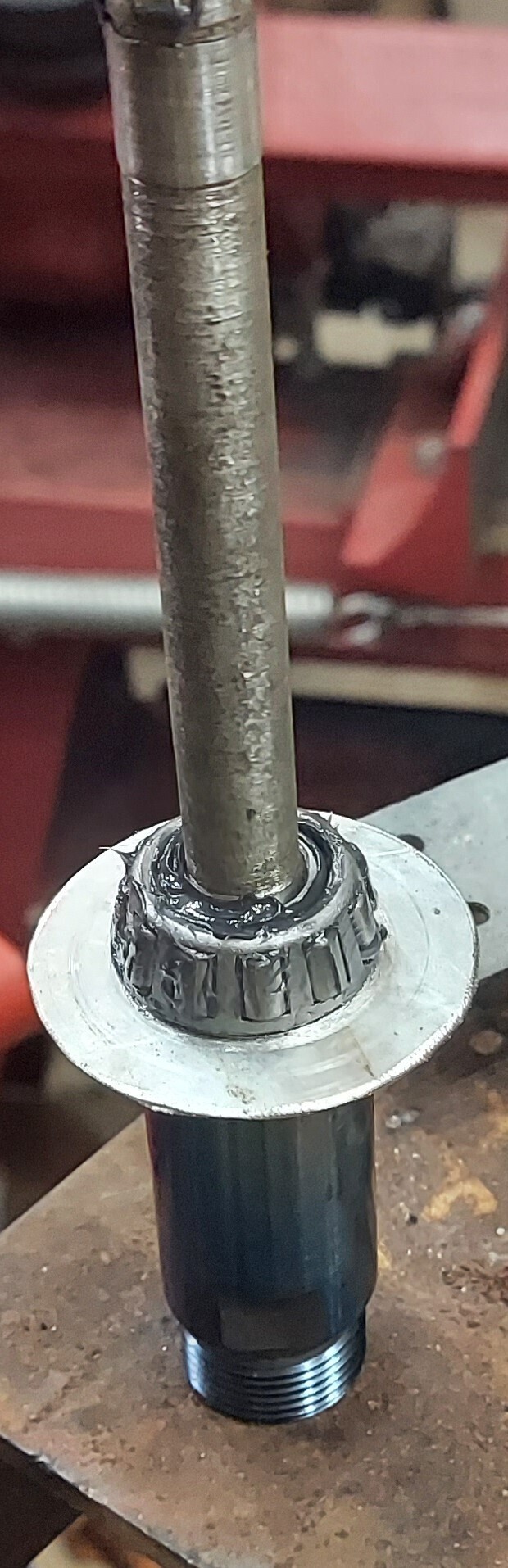
This worked about as well as I could hope. It prevents the grease from falling out and dust from getting in. A tapered roller bearing requires a certain amount of preload to force the rollers into the tapered bearing race. To get this, I added one shim from a package of standard shims that have the same inner diameters as that of the bearing. This combined with the alumimum spacer preloads the bearing a small amount.
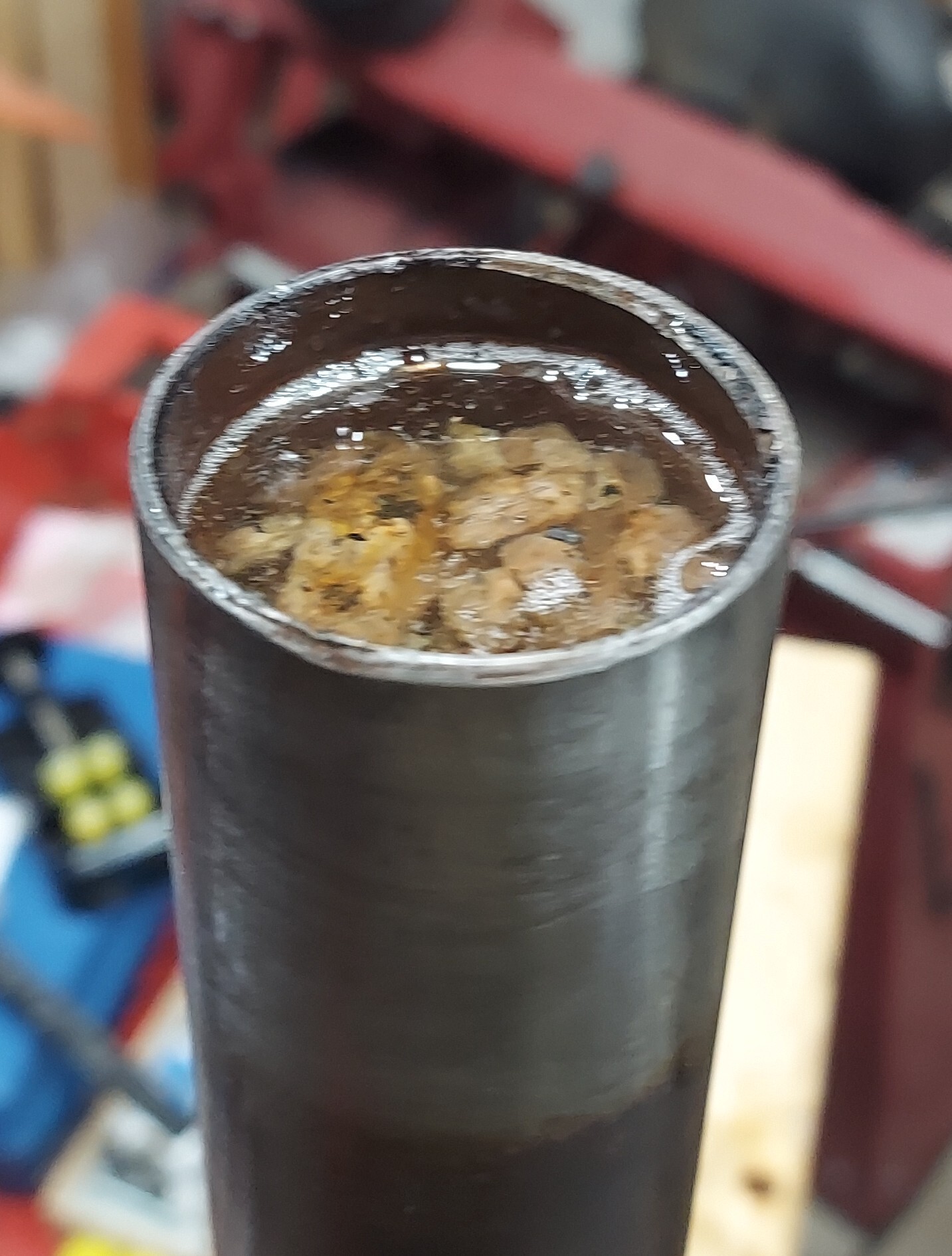
Removing rust
To remove rust, I just used scotch brite on the column. The base of the drill press was held up to a bench grinder with a wire wheel attachment.
Fiting a collet chuck
To mill metal, you use something like an end mill. This is usually held in something called a collet chuck. A traditional 3 jaw chuck like a drill press uses does not have enough contact to hold an end mill. Also, the chuck jaws are hardened and designed to bite the soft base of a drill bit. This won't happen on an end mill because the entire end mill is hardened. So the solution is to fit a collet chuck. A collet chuck uses an insert that is matched to the tool diameter rather than being adjustable like a drill chuck. A small mill would normally use something called an R8 spindle mount which locks into place. Drill presses always come with tapers, not spindle mounts. This is the taper of this drill press
If you know anything about drill presses, any real drill press comes with a morse taper. This morse taper on a drill press is internal taper. Inside that taper you can fit adapters to other tapers, drill bits, and even collets. This drill press does not have any kind of morse taper. The actual shaft taper is a "B16" taper as evidenced by the stamping on the original drill chuck. I did some hunting and it turns out someone makes a collet chuck that has a B16 taper. This allows an ER16 collet system to be used, which means cutting tools up to 3/8th diameter can be used.

So the good news is this presses right on, no problem. The bad news is it will never stay on because it is not a locking spindle mount like a mill should have. The forces involved in milling basically can be in any direction. This means it always works it way loose. I never intend to remove this, so I considered just welding it on. Before I tried that, I soaked it down with superglue gel and force the taper on. I gave it 30 minutes to set up and I've had absolutely zero issues since then.
I've realized the downside to this is that the B16 to ER16 adapter is huge commpared to even a drill chuck. There is no way to make it more comapct that I can see. So this limits the overall machine rigidity. If I had started from a drill press that used an MT2 internal taper I could have gotten an MT2 to ER16 adapter. These are much longer but fit up inside the quill. So it doesn't stick out so far.
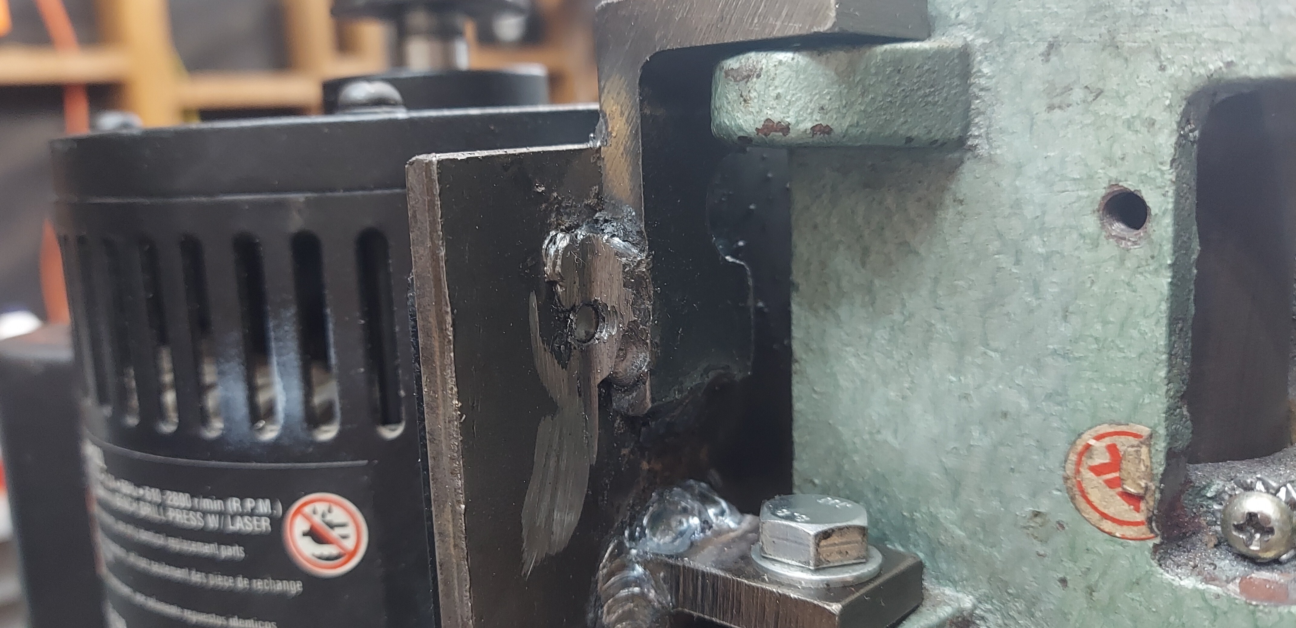
A Z-travel lock
The quill on a drill press is spring loaded and normally retuns to the highest position. This doesn't work in a mill since the cutting bit needs to be held in position. To create a Z-travel lock I cut off the tab where the travel indicator used to be. Then I drilled a hole and tapped it for a M10 bolt. I made a small handle that goes on this so I can quickly lock or unlock the Z-travel
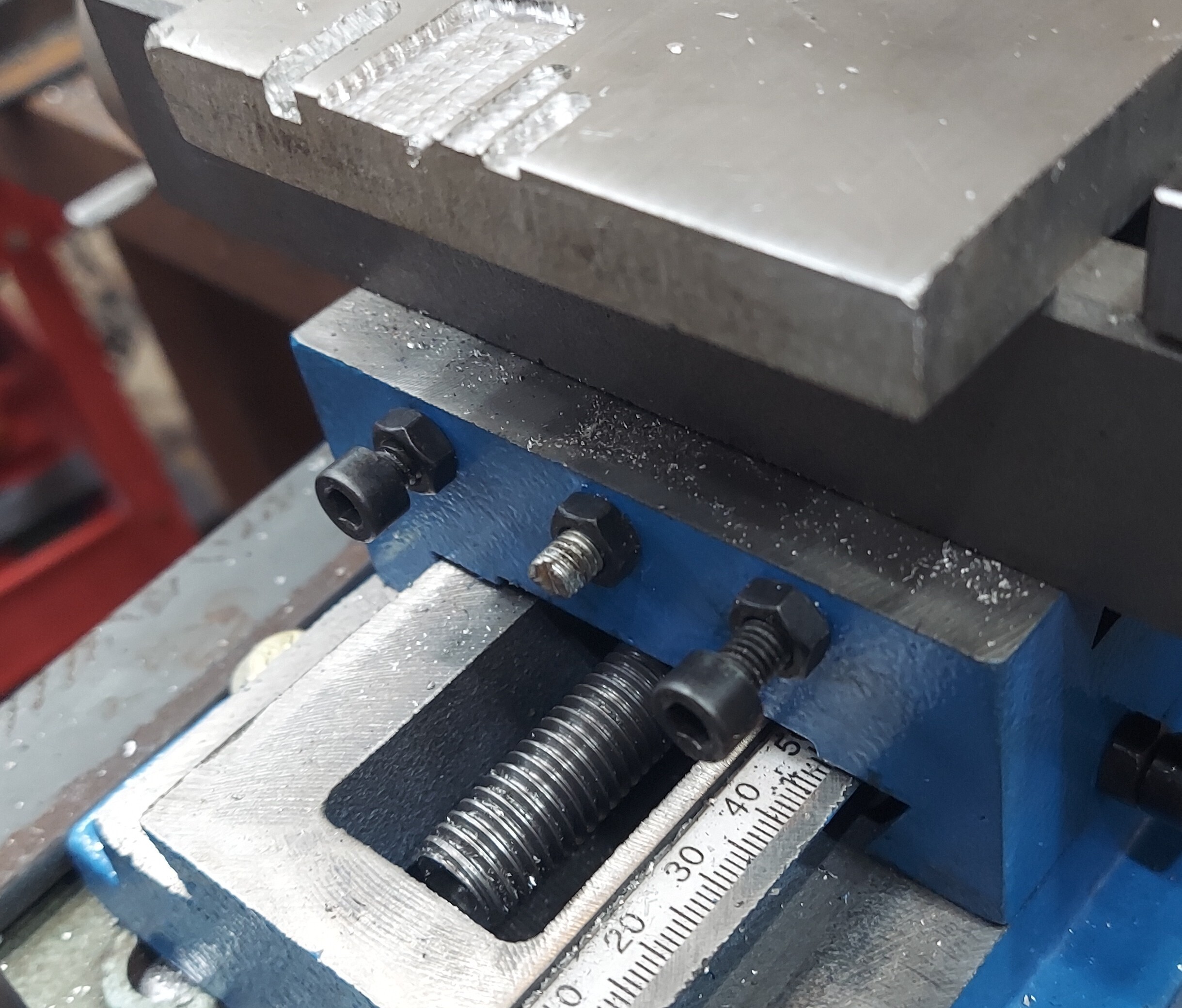
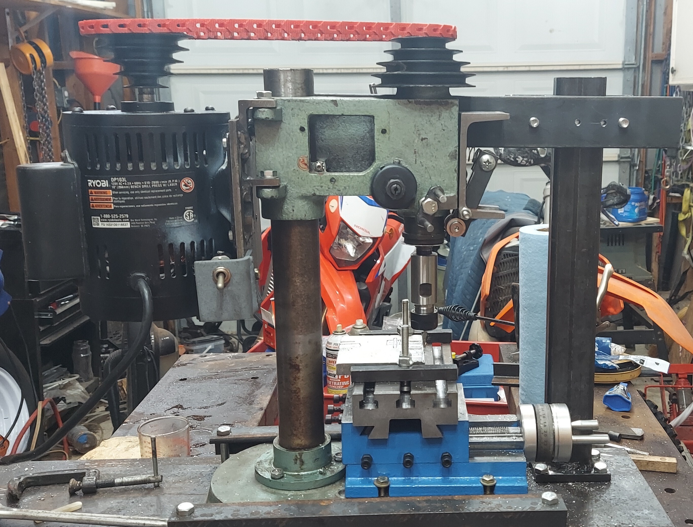
Adding an X-Y table
Drill presses always use a table that slides up and down a column. This table can be adjusted for differing sized workpieces as needed. I removed the table and threw it in my junk drawer because I have no intention of using it. I did some searching and found an X-Y table.
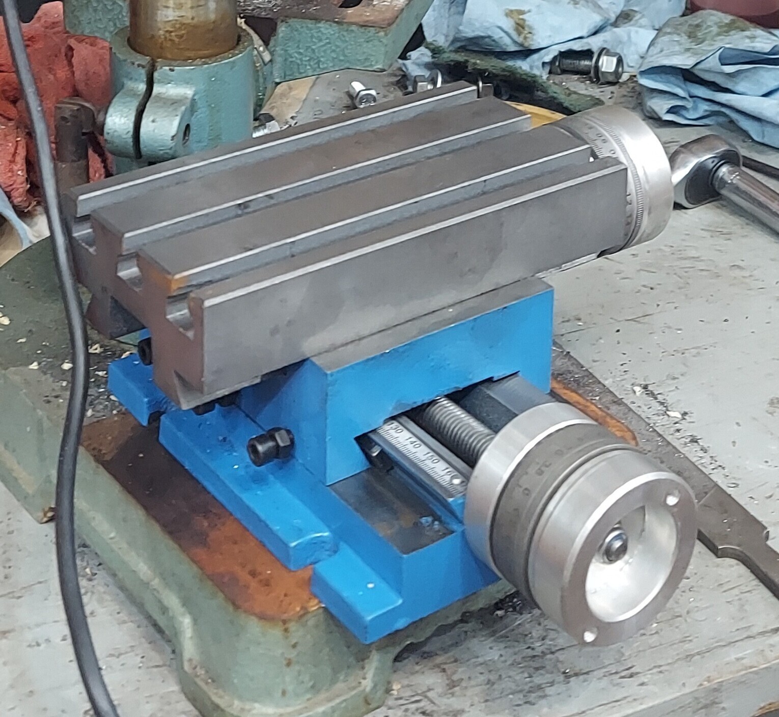
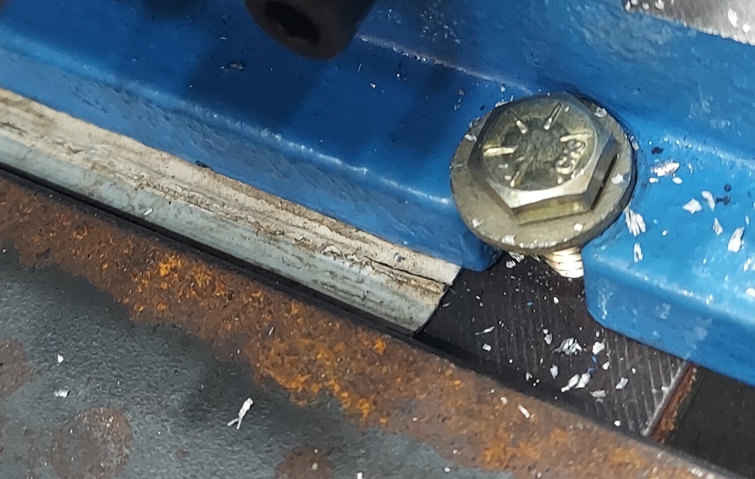
You can find this X-Y table sold on the usual outlets under many brand names. This particular one is branded as "VEVOR" and I found it cheapest on eBay. I drilled and tapped holes for 1/4-20 screws in the base. I used grade 8 hardware to hold the table in place.
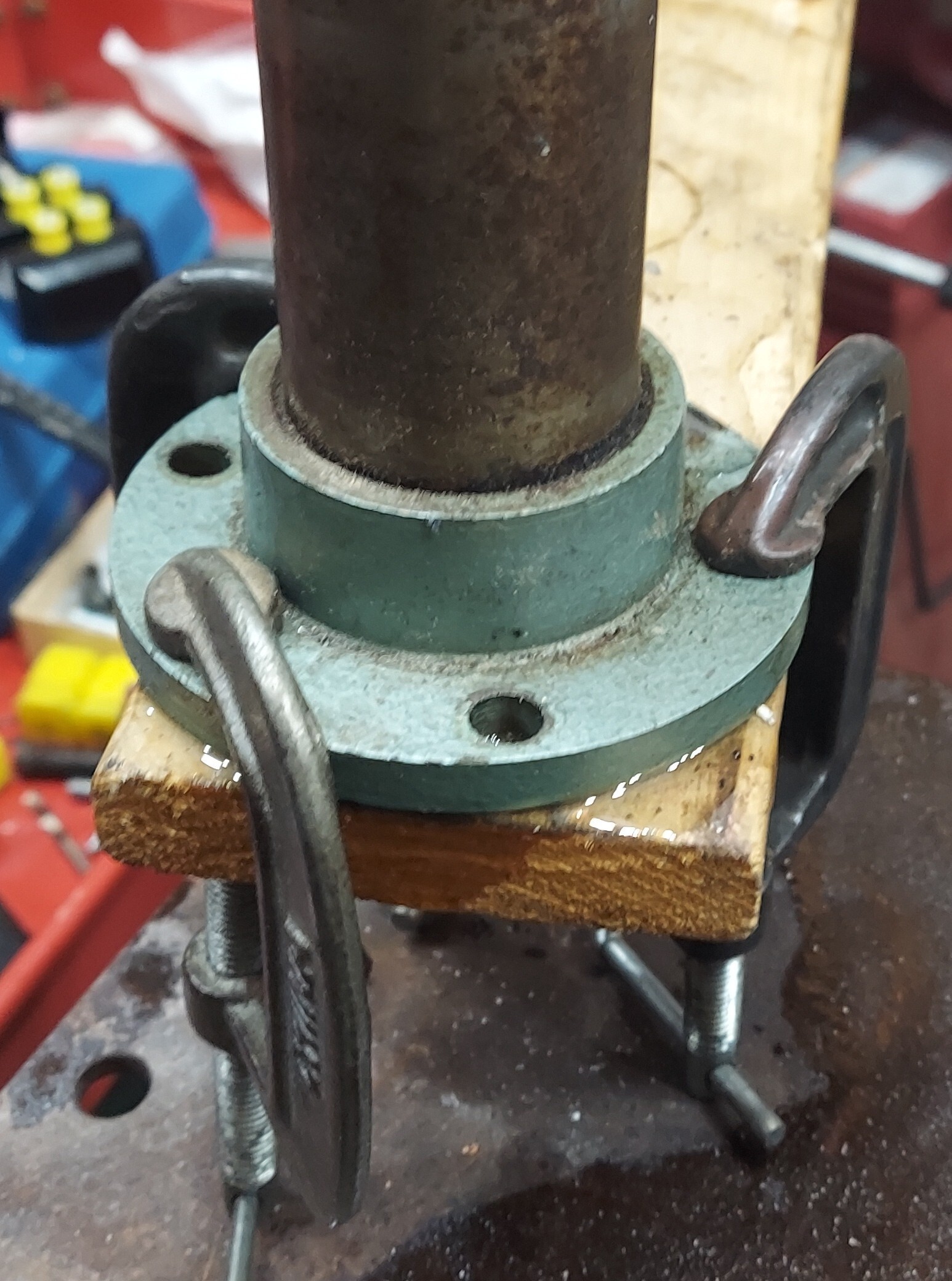
Clearancing the column to fit
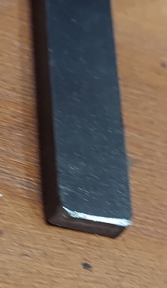
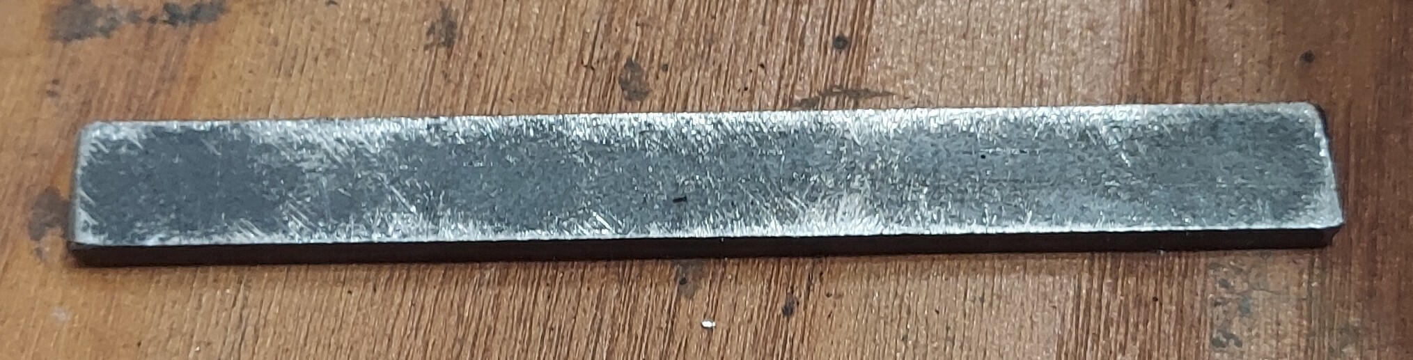
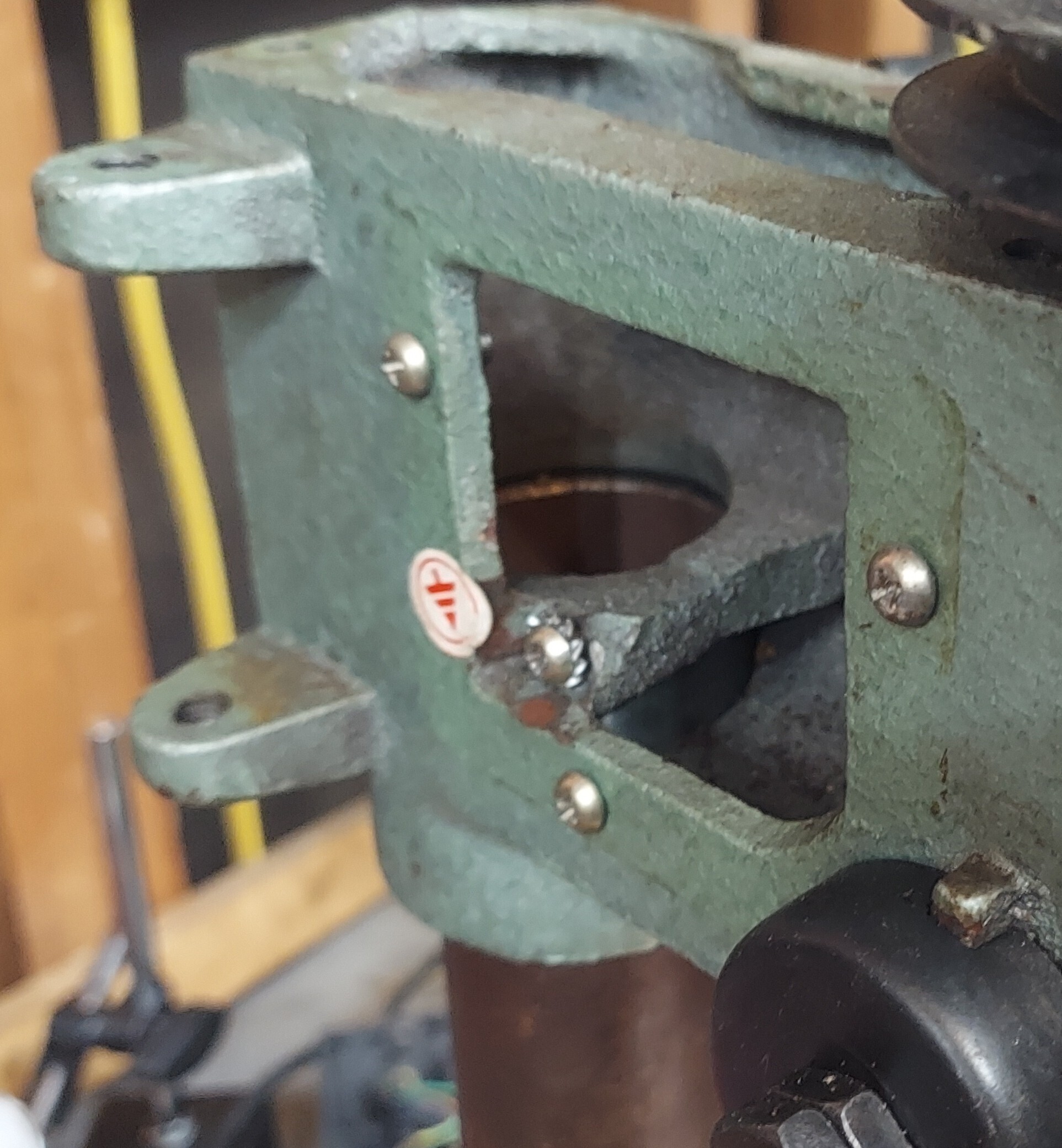
The first thing I realized was I needed to make space for this X-Y table on this tiny drill press. In order to gain a little space I ground a flat spot on the flange of the column base
Ignore the wood & the mess, that is discussed later
Fixing the gibs on the dovetails
Apparently precision (using that term loosely here) X-Y tables aren't made as two mated surfaces. To take up the final slack a piece of metal known as the "gib" is placed between two trapezoidal machined surfaces. Then the "gib screws" are adjusted to take up the slack. The problem is you need to actually have smooth surfaces for this. In this case the piece of metal supplied is just a stamped piece of steel. So it's actually pretty rough. What I did was to round off the ends using a metal file. I then placed the sliding side upwards on my work bench. I used a file to remove a bunch of material, working at a 45 degree angle to the major axis of the piece. This does not make it flat, but it should remove the lips on the edge from the stamping. After this I wipe everything clean and put some thin oil on it before re-assembly.
A future improvement would be to use the milling machine to actually make half decent gibs from small pieces of scrap steel.
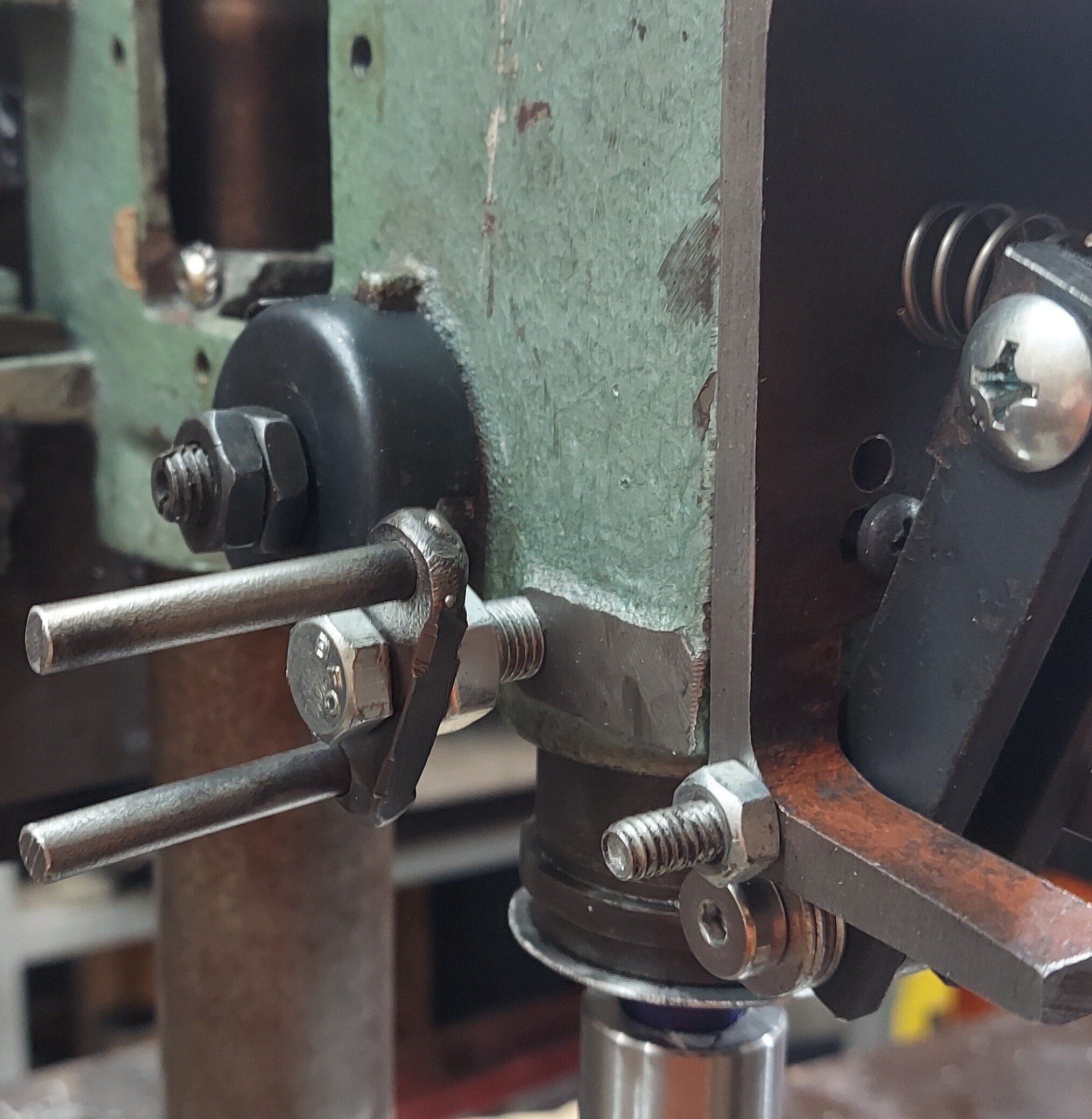
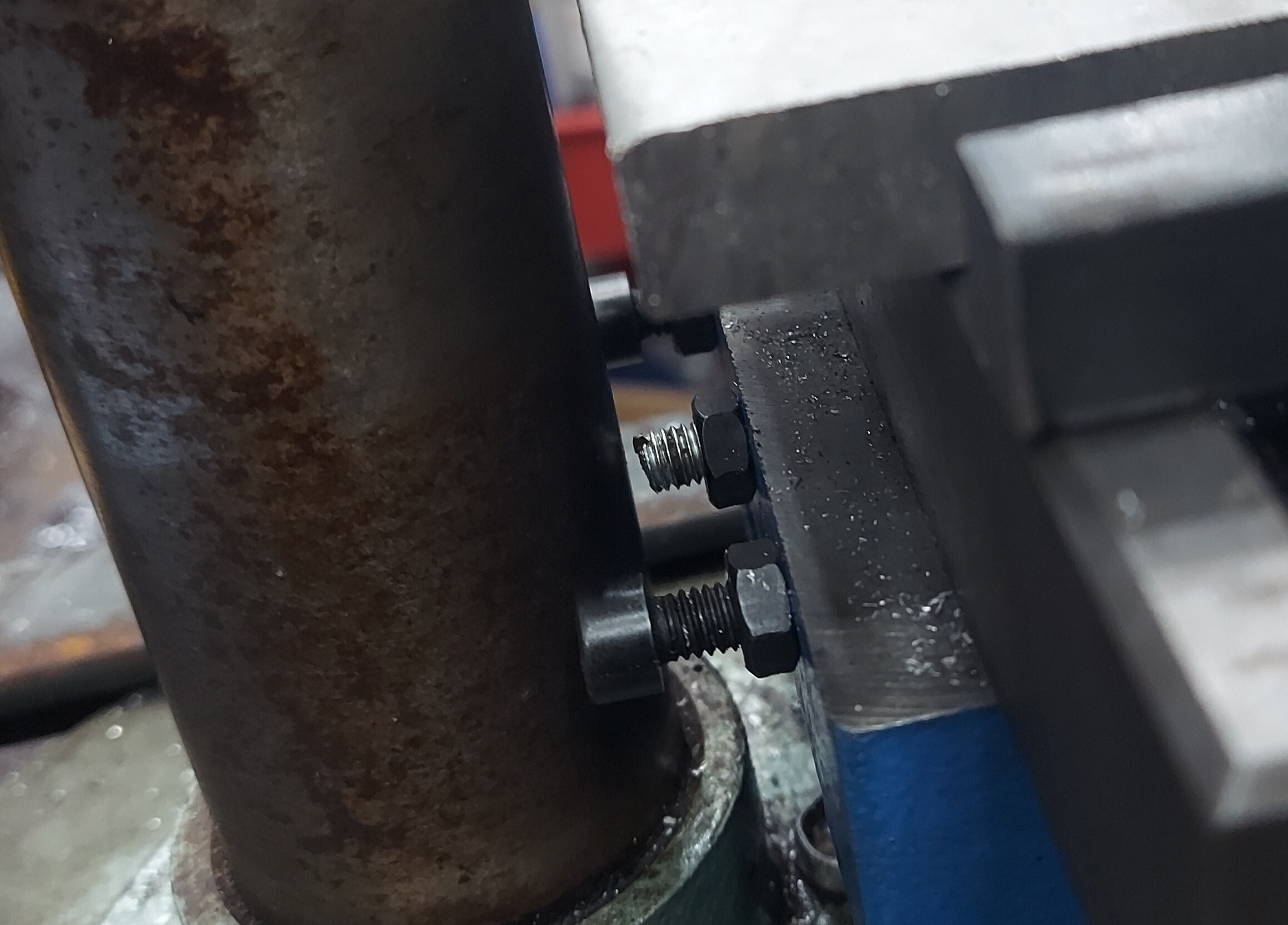
Clearancing the gib screws
Due to where I placed my X-Y table, at one end of the travel the gib screws hit the column. All gib screws are just M6 bolts. The lower ones are actually 32mm in length. To gain back some travel, I took some random bolt that was the right length and cut off the head. Then I slotted it so I could use a regular screwdriver to adjust it. This might seem insignificant, but even 5mm is a large percentage of the overall travel in this dimension.
Tramming the table
Just because the table is bolted to the drill press does not mean it is square to the tool held in the collect chuck. I put a machinist's square on the table so I could see how far it is out and in what direction. I ended up just slipping a piece of aluminum material under one side and then tightening the screws down. This got it very close to tram which works for now.
In the future I am going to try and buy some actual machinists shims in different sizes to make this work.
Converting the Z axis to be adjustable
The drill press has the quill that moves up and down. This doesn't provide enough travel since I am not planning on using the drill press table. I originally was going to cut the column. It was simpler however to grind out the internal lip on the drill press casting that prevent it from traveling downwards. After that I can simply lower the casting to any position I want. So I have the entire height of the column as Z travel now. I did this with a dremel tool and a carbide burr. It took entirely too long and actually made a huge mess because the original casting is "gray iron".
Preloading the quill
The quill on this machine has tons of slop. I need some way to eliminate this. So I made this contraption from scrap. What this does is uses a 608 bearing in a spring loaded arm to hold the quill to one side. This is crude but works well enough for what I'm doing.
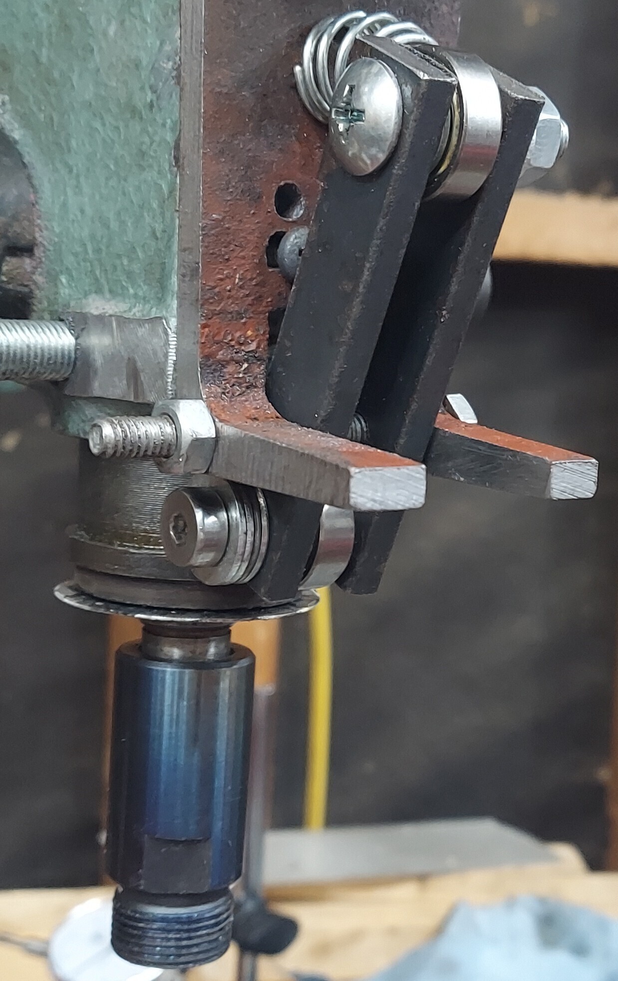
In the future I can probably improve this quite a bit but making it have 3 points of adjustable contact spaced evenly around the quill.
Improving machine rigidity
The column on the table isn't very rigid. If you look at big vertical mills they usually use a square column that is more rigid than a round column used by a drill press. When I would try and mill stuff the whole upper structure would resonate as I moved the cutter into the material. I thought about many ways I could fix this but they all were impractical. So I ended up adding a second column in front of the drill press.
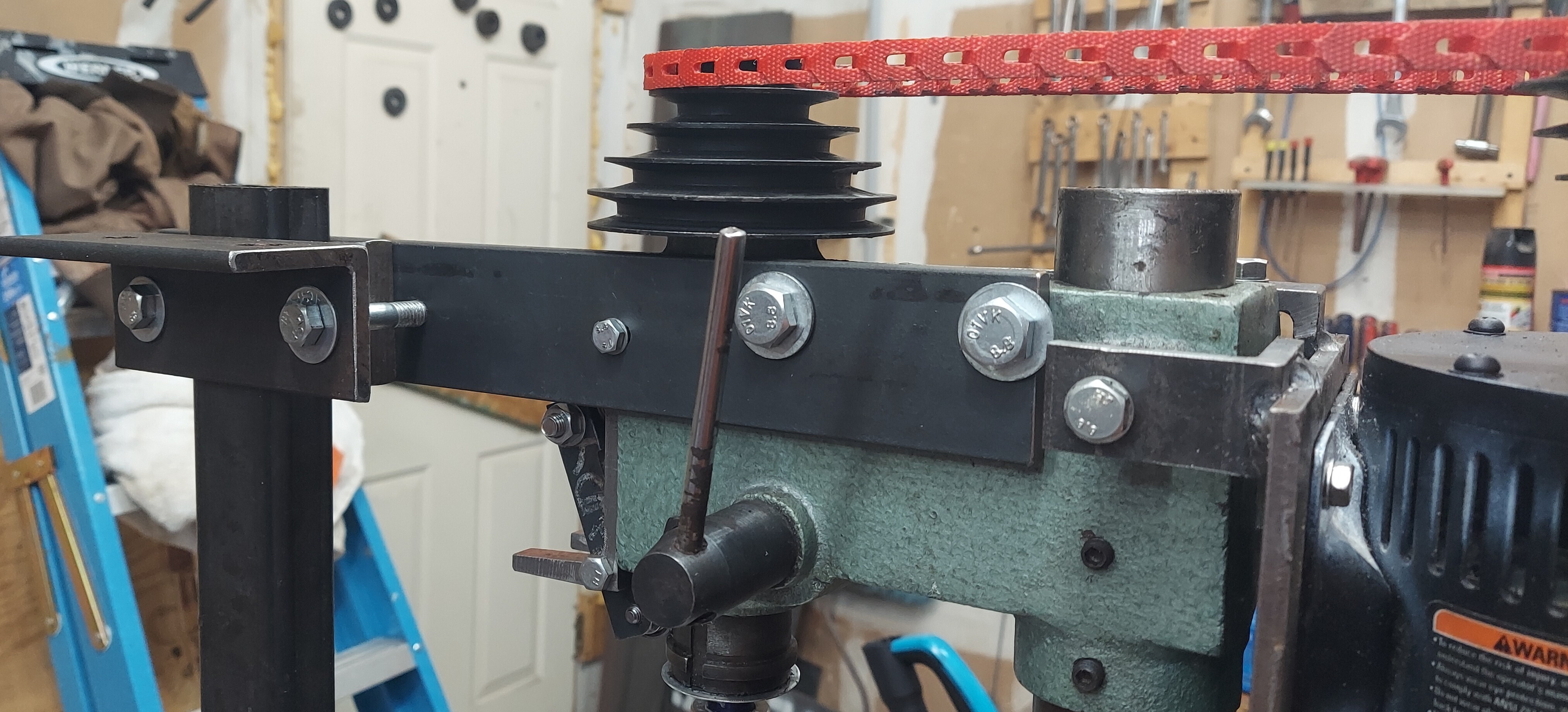
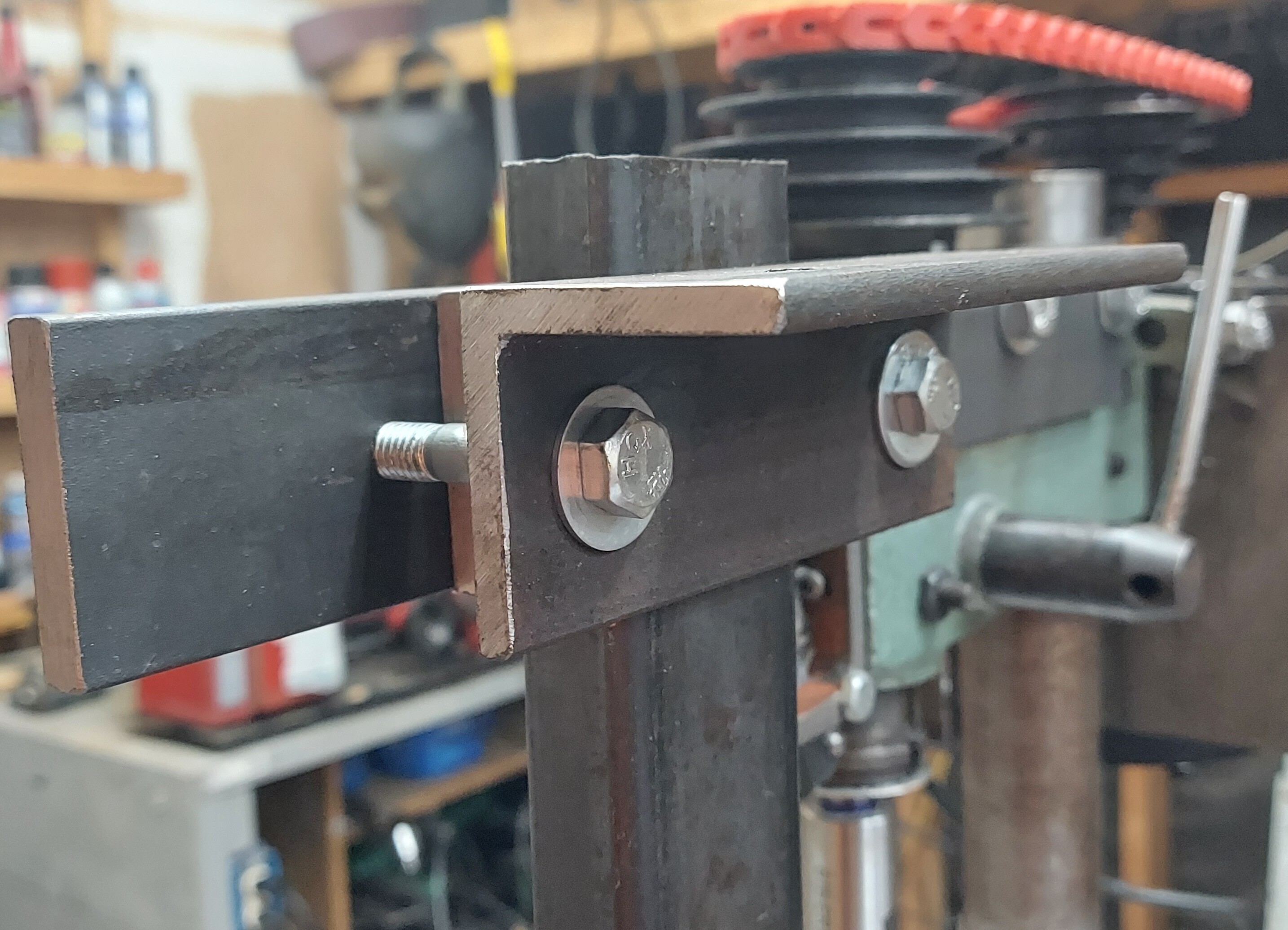
All this is is some scrap steel I bolted to the drill press. This gives me the ability to clamp to a front column. This converts the normal drill press structure that is basically a C-clamp into a square. Its substantially more rigid. All I needed to buy was some fasteners for this. There is no precision work because I setup the drill press with the column first then clamp the secondary column in place last. Yes, it's kind of in the way but I'm not planning on trying to bolt down an engine block to this any time soon.
The front column doesn't have anything to bolt to. So I found a huge piece of C-Channel I had and made some "clamps" to hold down the whole drill press base to that. I call this the "sled". I bolted the front column down to that.
I do not know how much this weighs but it is at least twice the original weight
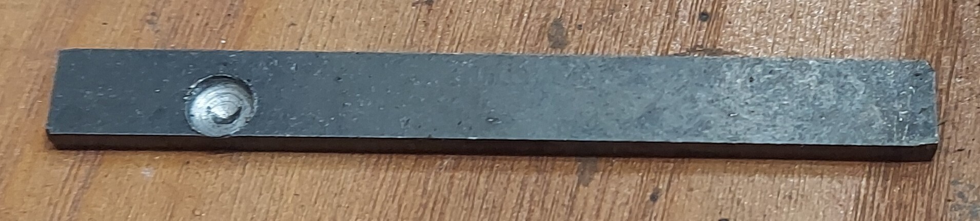
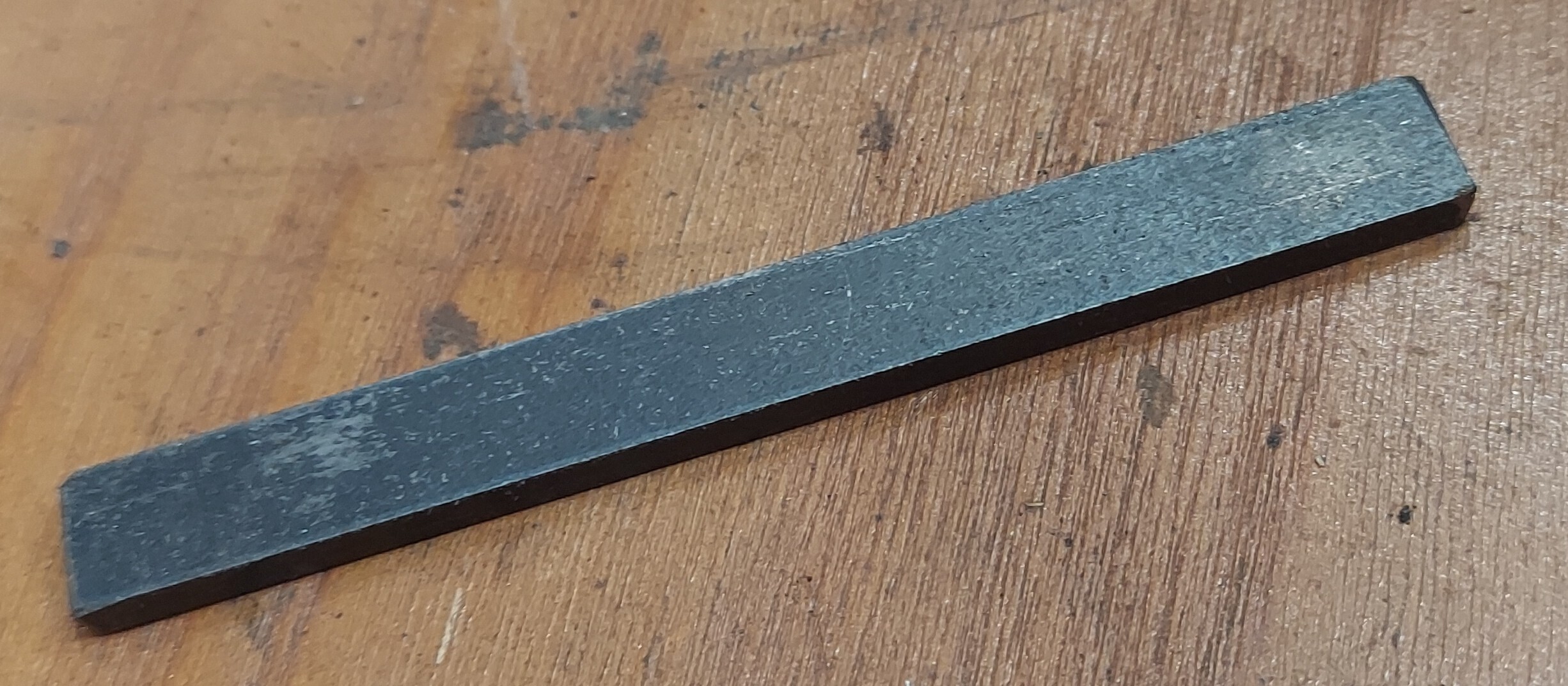
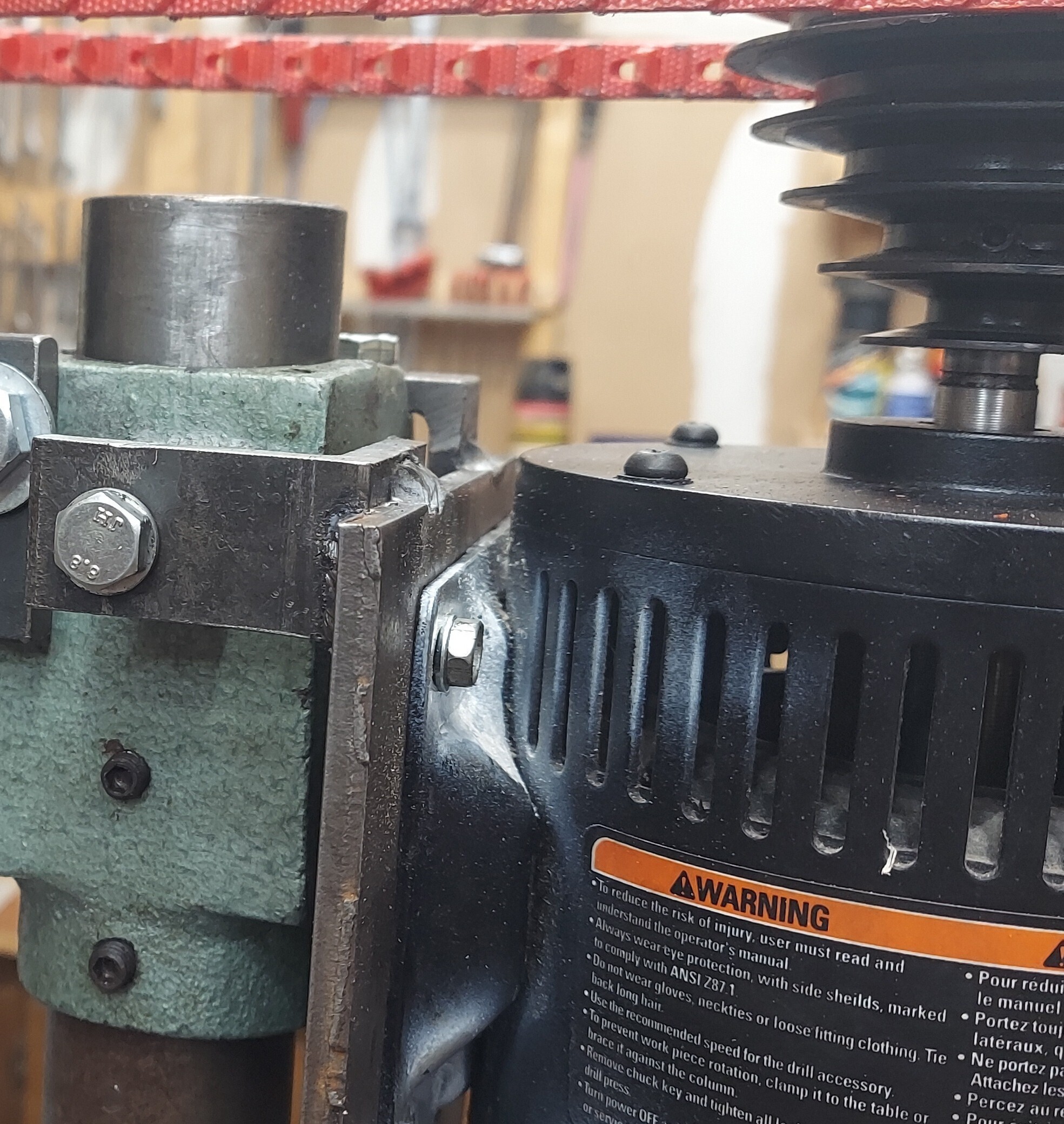
Upgrading the motor
The original motor was quite awful. It was around 1/3 HP according to the label. Not nearly enough power. I'm also fairly certain it was never balanced at the factory.
The original motor's label
So I found a motor on facebook marketplace that had the same shaft size off a newer drill press. It cost me $20. I had to put new bearings in it but that was easy. I made a new motor plate from 1/4 steel I had. The original drill press tried to have the entire motor adjust. This isn't really practical. So I used the two "hinge" bolts they had and then picked up a third bolt from the set screw for the sliding pin. So the motor is now fixed in position. Since the motor can't be moved I ordered a 3/8th link belt. This is a belt you can make shorted by just taking out "links" which are just made of some sort of flexible material. This motor makes more torque and has twice the rated RPM.

Eliminating vibration with polymer concrete
At this point I actually had the machine rigid enough to use. But it still vibrated like you wouldn't believe. So I did some research and apparently the solution to this is to use something called "polymer concrete". This comes in many forms. The basic idea is to fill the voids of the machine with anything that can dampen vibration. The easiest way to do this is to mixup some sort of material that sets like concrete and other vibration damping media.
Selecting a resin
In order to put material into the voids of the machine we need something we can pour in place. The most common material would be portland cement. This is cheap but tends to shrink when curing. The next most common is polyester resin. This too shrinks. I ended up buying epoxy resin from West Marine since they were the only place I could locally get a small quantity. It wound up costing $80 for this.
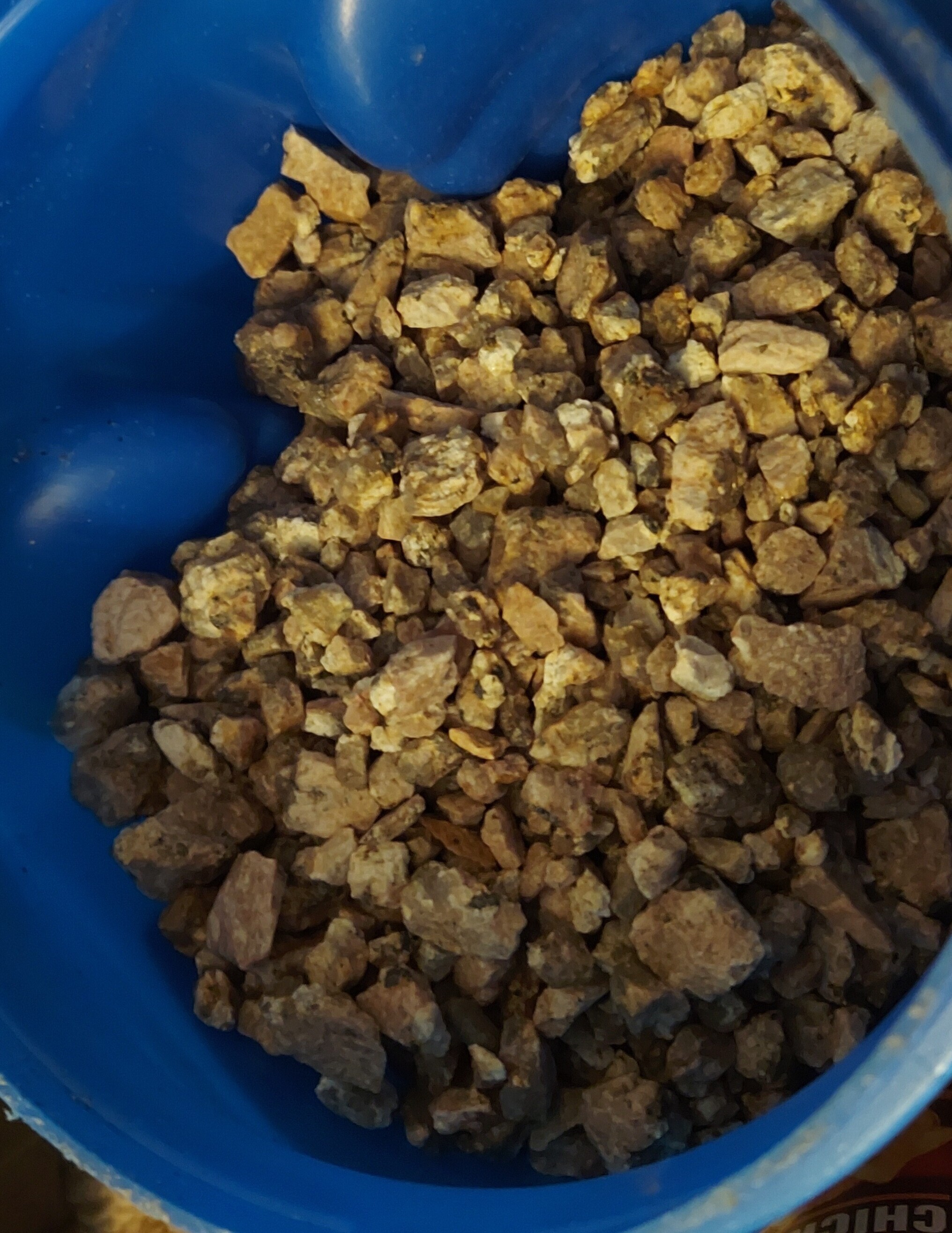
Finding a source of granite
You could probably order high quality granite, but I just bought a 40 lbs bag of decompsed granite for $5.58. It's mostly water by weight from what I could tell. I used some sieves to separate out different size rocks from 1/2 inch all the way down to around 1/8th inch. The extremely fine dust was washed off the rocks and then I spread them out indoors to dry them out. So at this point I had probably 15 lbs of clean granite rocks of differing sizes.
Pouring it full
So I decided to fill 3 components of the machine
- The round column
- The square column I added to the front
- The base of the machine
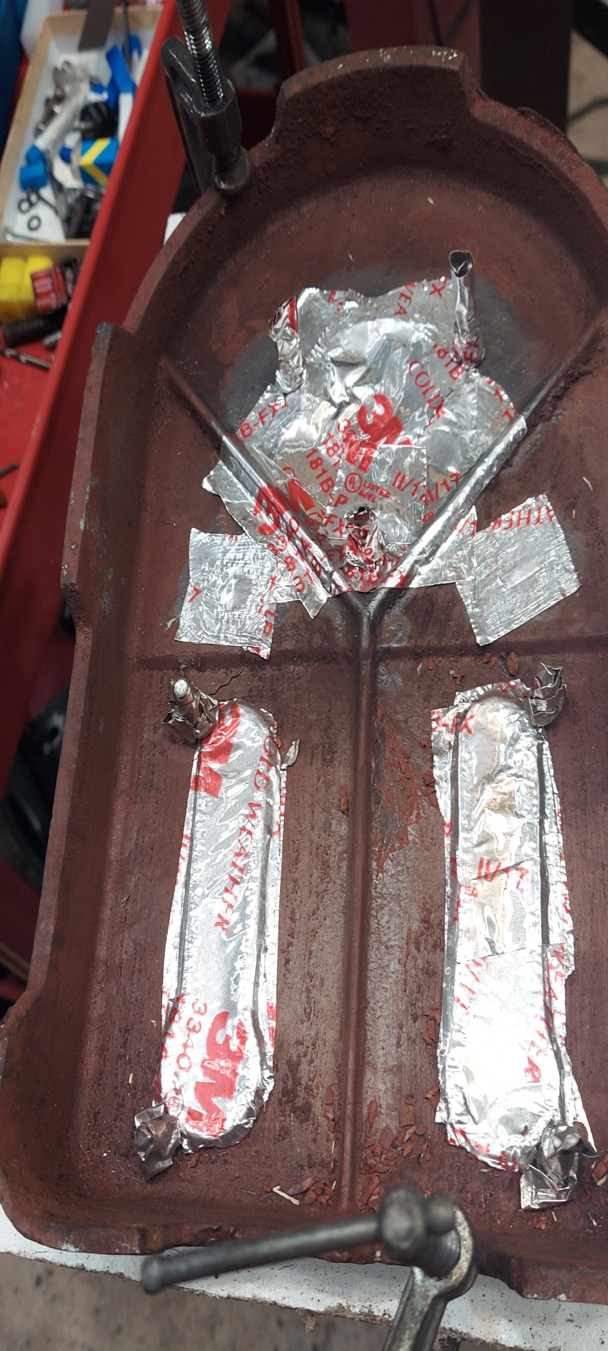
Filling the base was the hardest part of this. There was what appeared to be a thick coat of primer left over from the factory. So I stripped most of that off. It has a bunch of slots and holes. Some I wanted to keep, some I wanted to eliminate. To eliminate the slots or holes I covered them with aluminum tape. To keep the holes I threaded in long fasteners and covered them with several wraps of aluminum tape. The fasteners should ideally come up above the maximum level of the polymer concrete.
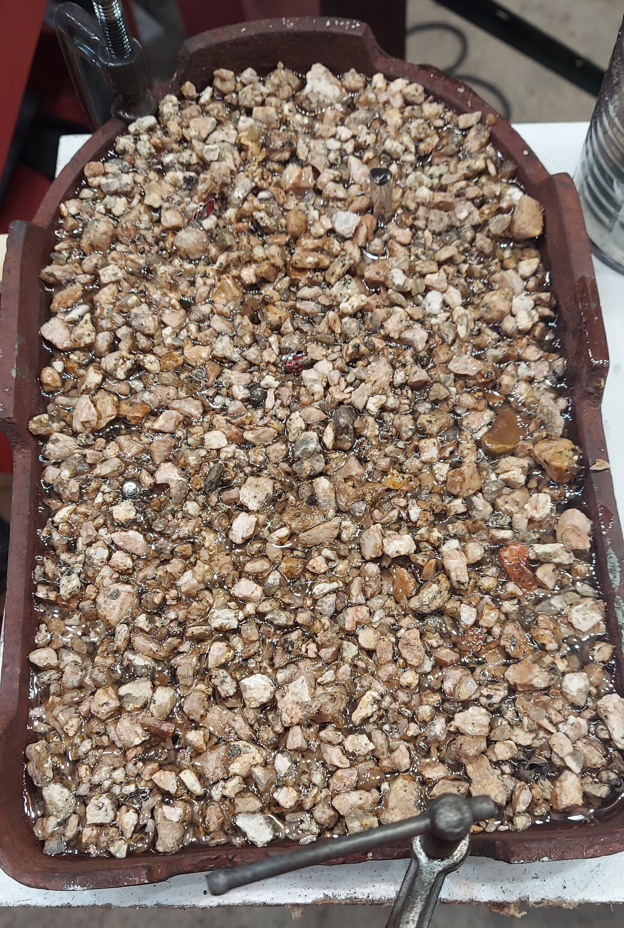
I flipped the base over and poured it full after making sure it was sitting level
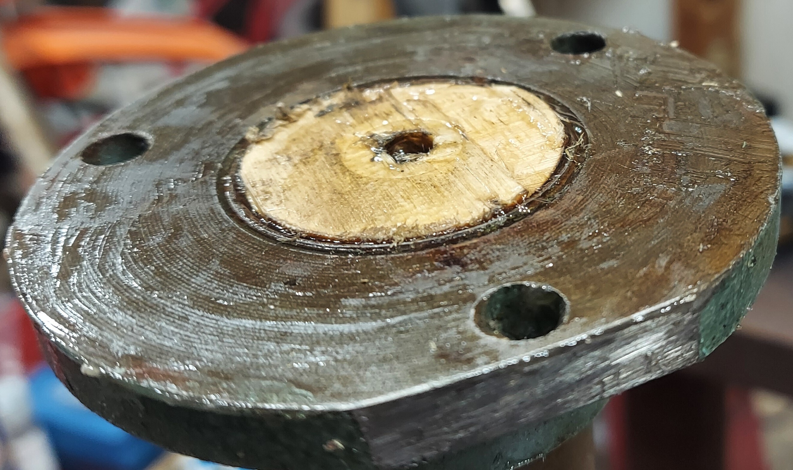
To fill the square column I just sealed the base up with the welding machine and then poured it full. I alternated epoxy and material when adding it.
The round column is open on both ends so I made up a wooden plug and used that with a lag screw in it to seal up one end. I ended up clamping another pice of wood to the bottom as stuff still leaked out.
Improvements to this process
I learned a few things along the way working on this.
The first thing is when mixing epoxy resin you need to be very precise about the amount of resin and hardener you combine. I didn't get this right when making the columns and they took forever to harden.
The next thing I learned is that you shouldn't rely on 100% resin to fill the voids between the rocks. It's too expensive and not actually very good at dampening. I think for a small project like this I would just get some sandblasting media from somewhere in a small quantity and use that. You can mix it into the epoxy resin before pouring it in.
The last thing I thought about was how I filled the column. This took me a while to realize, but I could have made this much more rigid. The way I did this it still separates from the base. There is absolutely no reason for this. If I did this again what I would do is plug the top of the column with wood. Then I would use permanent loctite to install the bolts holding it to the base. Then the entire structure could be flipped upside down. At this point you could fill the entire thing with polymer concrete. It'd basically be one giant polymer concrete casting at this point.
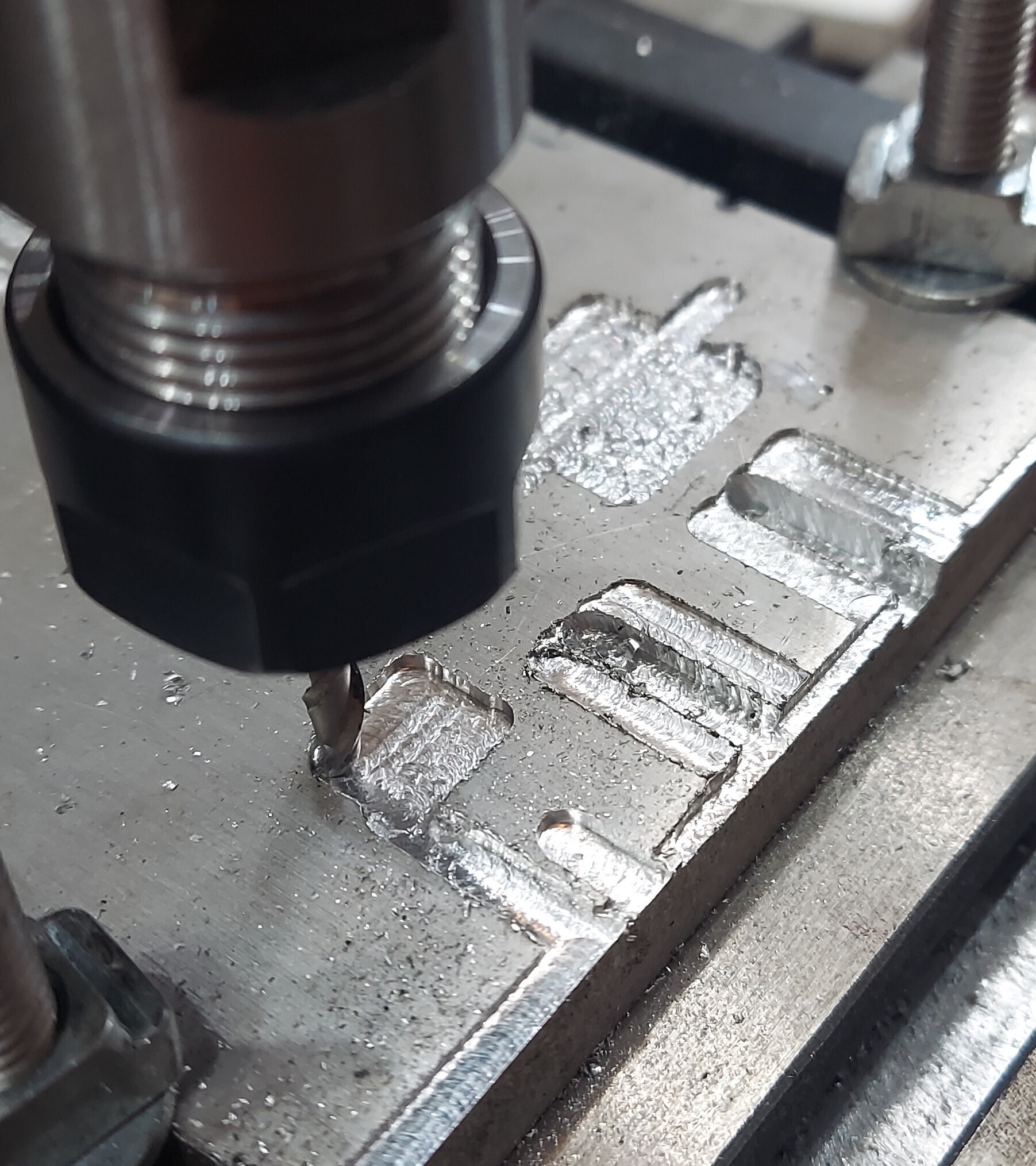
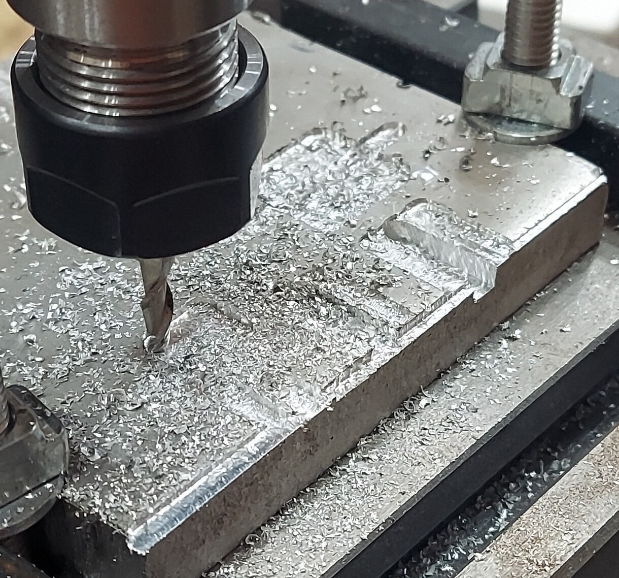
Making chips
So at this point this contraption was "complete" or I decided not to put more effort in it presently. I experimented around with cutting some aluminum with different bits. You can get cheap HSS bits on eBay that work decently well. But what I did was found some cheap 3/16th 2 flute cutters made from M42 alloy. This is a cobalt steel alloy that is extremely durable.
So it works. Not as well as a real machine. I quickly figured out that I can only really do climb milling with this otherwise I get huge amounts of deflection from the tool holder. For my first real cut I decided to use the mill to face off one end of a piece of brass stock. This is going to be used to make an antenna mount
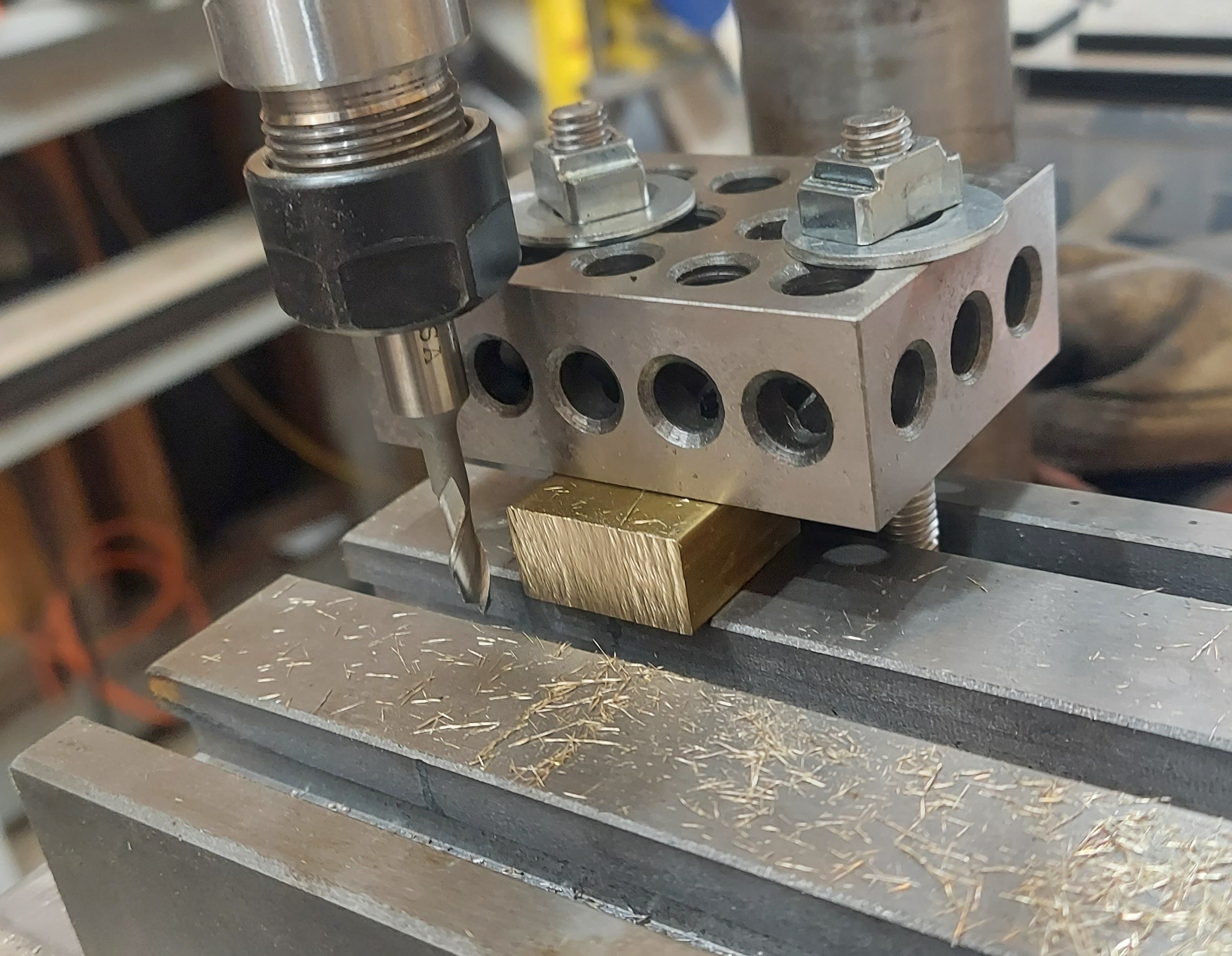
In order to clear the 1-2-3 block I was using as a hold down I had to have the tool sticking way out. I ended up with lots of chatter due to this and got a poor finish. But I was actually able to square off the end.